- Community
- Creo+ and Creo Parametric
- 3D Part & Assembly Design
- Partial Bend Back
- Subscribe to RSS Feed
- Mark Topic as New
- Mark Topic as Read
- Float this Topic for Current User
- Bookmark
- Subscribe
- Mute
- Printer Friendly Page
Partial Bend Back
- Mark as New
- Bookmark
- Subscribe
- Mute
- Subscribe to RSS Feed
- Permalink
- Notify Moderator
Partial Bend Back
I have a part that has three states.
Flat Pattern
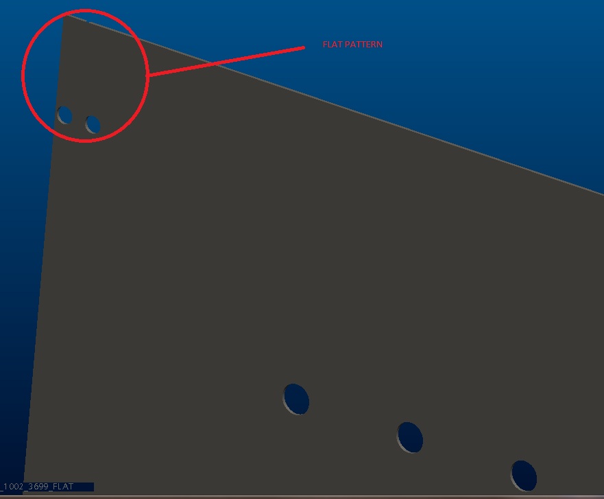
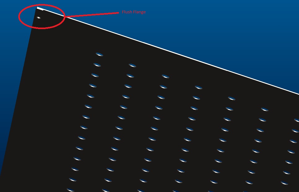
Flush Flange on a Flat.
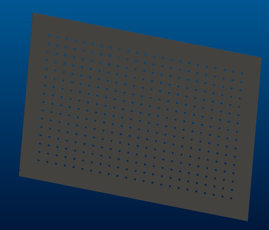
As installed.
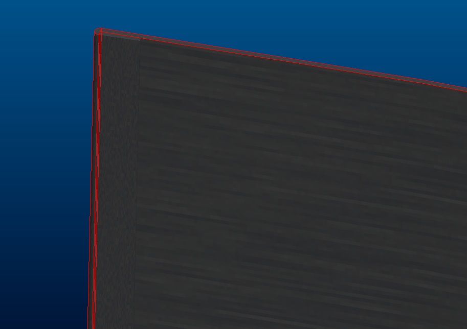
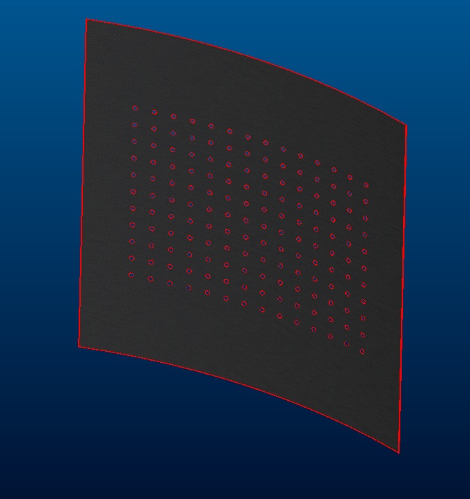
Is there a way to do a partial bend back on just the flanges and leave it in the Flush Flange on a Flat for the drawing? In other words, if created in the as installed state, I can get the flat pattern, but how do I get the flat part with the flush flanges showing?
Thanks, Dale
FYI (Currnetly I have different models and I would like to get this to one model in a table where I can turn on/off flat pattern or bend back features.)
This thread is inactive and closed by the PTC Community Management Team. If you would like to provide a reply and re-open this thread, please notify the moderator and reference the thread. You may also use "Start a topic" button to ask a new question. Please be sure to include what version of the PTC product you are using so another community member knowledgeable about your version may be able to assist.
Solved! Go to Solution.
- Labels:
-
General
Accepted Solutions
- Mark as New
- Bookmark
- Subscribe
- Mute
- Subscribe to RSS Feed
- Permalink
- Notify Moderator
Here is what I ended up doing to get this to work.
I rolled the part back to before the bend back that made the whole part curved and with both flanges. I then started a bend back. For the fixed geometry, I selected the long edge of the soft curve. I then chose BendBack Sel, then Done. The selected geometery for this was the small portion of material where the flush flange started. Holding the Ctrl and selecting the second flush flange.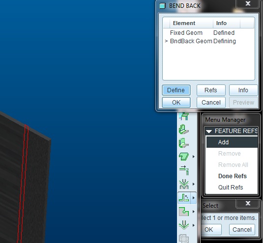
Then select done.
I rolled the tree forward and the complete roll back failed.
I added the two unbends to a family table and for middle model - flat with flanges, Y for the partial unbend and N for the complete unbend. For the curved part, I reversed the two options. For the completed flat pattern, I used the complete unbend and then had a flat pattern.
This worked to get the three states of the model that I needed.
- Mark as New
- Bookmark
- Subscribe
- Mute
- Subscribe to RSS Feed
- Permalink
- Notify Moderator
Why not use view states where the "final" version is the installed state, but various drawing versions will show what they need to show.
- Mark as New
- Bookmark
- Subscribe
- Mute
- Subscribe to RSS Feed
- Permalink
- Notify Moderator
I guess that is what I would like to achieve. The question i have is how to get the middle state. In fact when I was first creating this part last summer, someone on the board suggested that I start with the curved part and the unbend to create the holes and their patttern and the bend back to get the curved part that I have in the final version. Then at the end of the tree, I have the flat pattern that I can resume to get that state. What I am looking for help is how to break up the bend back into separate features. One feature would be to bend back the flush flanges (middle state) and the other would be to bend back the flanges and the curvature of the part. Is that possible?
Or do I need another approach?
- Mark as New
- Bookmark
- Subscribe
- Mute
- Subscribe to RSS Feed
- Permalink
- Notify Moderator
I suppose it is all about technique. I am suggesting going all the way by creating the flange twice by cutting it off the 1st time and creating the final version. In view states, you can disable whatever you don't want to see.
- Mark as New
- Bookmark
- Subscribe
- Mute
- Subscribe to RSS Feed
- Permalink
- Notify Moderator
Forgive my ignorance:
The flange exists in all states: the final state (curved), the flat state (middle), and in the flat pattern (as laser cut). The curvature for the part comes from installing the flat part into a groove and "bending" it until it fits into another groove.
When you say "cutting it off" (the flanges), are talking of suppressing the flanges in the final state, unbending it and creating new flanges at that state?
- Mark as New
- Bookmark
- Subscribe
- Mute
- Subscribe to RSS Feed
- Permalink
- Notify Moderator
Clearly I am not following the needed states or where you are having trouble.
I see the sheetmetal module as a series of bends and unbends based on the deisng requirements. You should be able to drive it to the "final form" that you want to use it in your assembled (next level assembly) model.
If that is not the final fabrication state, then you can disable that final soft bend in a view state and now you have a completed fabrication state. This is where the flat pattern falls down, if I recall correctly, because you cannot put flat pattern feature in the middle of the tree. So the bend for the soft curve needs to happened near the end of the tree so you can disable it and till have the fabricated state.
- Mark as New
- Bookmark
- Subscribe
- Mute
- Subscribe to RSS Feed
- Permalink
- Notify Moderator
This part was started before I came here and I am trying to understand it.
Currently the soft bend is one of the intial features in the part. A sketch defines the profile, then first wall, that sets the part in the curved state. The two side flanges were added. The part was unbent to add the hole perforation pattern (so that they woud be perpendicular to the part in the flat state). Then it was bent back. The powers that be now decided that the part, which was initially manufactured with a curvature, will be purchased flat and just installed so that it curves.
I am not trying to warp the model that was created for prototype parts in the flat state with the original bent configuration.
The drawing will show the flat (as purchased) part while the curved part will be for customers who want to see the visualization in the install state.
Since the part has the soft curve as its initial feature, that is where I am running into issues with the method that you are proposing.
If I take the flat part that I currently have (the model used for prototyping) how would I add the soft curve that you mention should be at the end?
- Mark as New
- Bookmark
- Subscribe
- Mute
- Subscribe to RSS Feed
- Permalink
- Notify Moderator
I am not familiar enough with the soft bends such as that to provide an accurate procedure. Since you have the original, I would suggest that it is done in the same way only at a much later state. I remember doing something to this effect using the Bend command and dragging the sliders to achieve a full curve.
We should start a poll...
How often do you have to revise a part where the revision required major changes to one of the 1st features (?)
- Never
- Sometimes
- All too often
- Every freak'n time!
![]()
- Mark as New
- Bookmark
- Subscribe
- Mute
- Subscribe to RSS Feed
- Permalink
- Notify Moderator
...or you could try a form feature on the last step ![]()
- Mark as New
- Bookmark
- Subscribe
- Mute
- Subscribe to RSS Feed
- Permalink
- Notify Moderator
Here is what I ended up doing to get this to work.
I rolled the part back to before the bend back that made the whole part curved and with both flanges. I then started a bend back. For the fixed geometry, I selected the long edge of the soft curve. I then chose BendBack Sel, then Done. The selected geometery for this was the small portion of material where the flush flange started. Holding the Ctrl and selecting the second flush flange.
Then select done.
I rolled the tree forward and the complete roll back failed.
I added the two unbends to a family table and for middle model - flat with flanges, Y for the partial unbend and N for the complete unbend. For the curved part, I reversed the two options. For the completed flat pattern, I used the complete unbend and then had a flat pattern.
This worked to get the three states of the model that I needed.
- Mark as New
- Bookmark
- Subscribe
- Mute
- Subscribe to RSS Feed
- Permalink
- Notify Moderator
Amazing what a little logic can do, huh ![]()
I am still not comfortable with family tables. Never really had a call to use them. I will see if I can find a few good tutorials and play with some screw families.
I like the view states. It is a bit more dependent on the historical order, and I want the default state to be the as-used state. The process of creating view states is also a bit criptic but once you get them to show up, it is easy to manipulate. They work very well in drawings and you never get bothered with choice when you assembly the part or get different saved files.


