Community Tip - Have a PTC product question you need answered fast? Chances are someone has asked it before. Learn about the community search. X
- Community
- Creo+ and Creo Parametric
- 3D Part & Assembly Design
- Pattern around cylinder
- Subscribe to RSS Feed
- Mark Topic as New
- Mark Topic as Read
- Float this Topic for Current User
- Bookmark
- Subscribe
- Mute
- Printer Friendly Page
Pattern around cylinder
- Mark as New
- Bookmark
- Subscribe
- Mute
- Subscribe to RSS Feed
- Permalink
- Notify Moderator
Pattern around cylinder
How to pattern around a cylinder without the parts flipping sides?
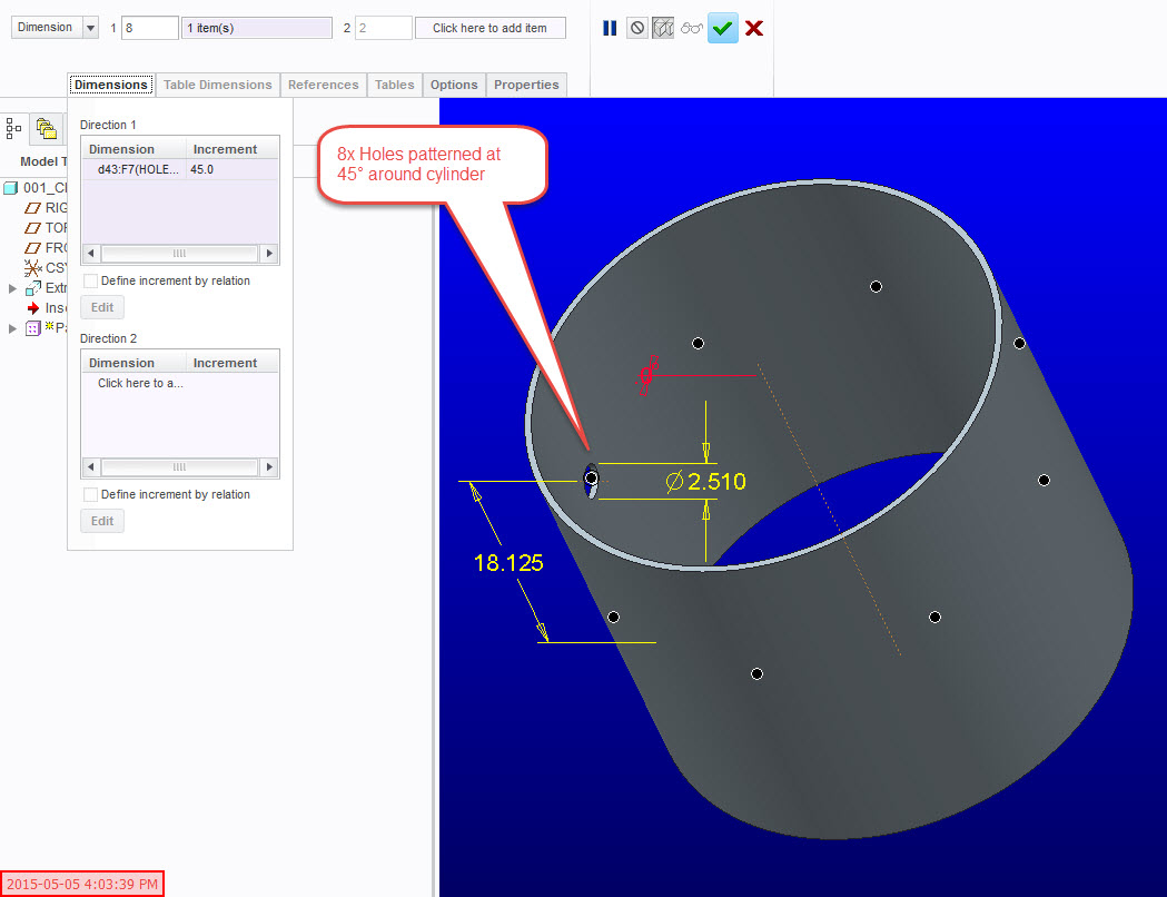
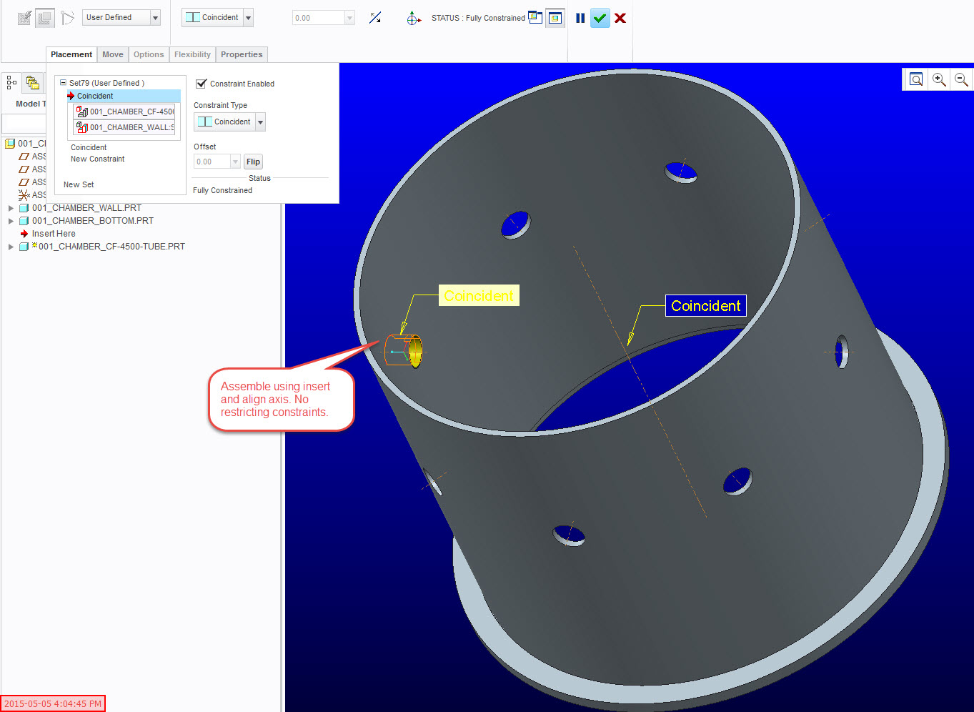
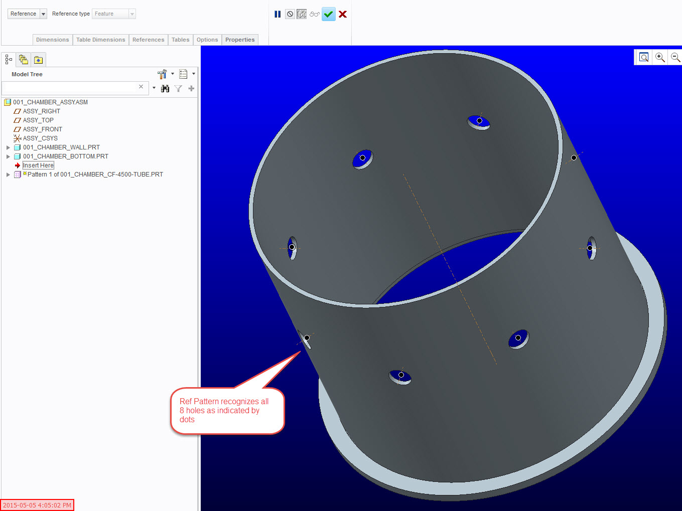
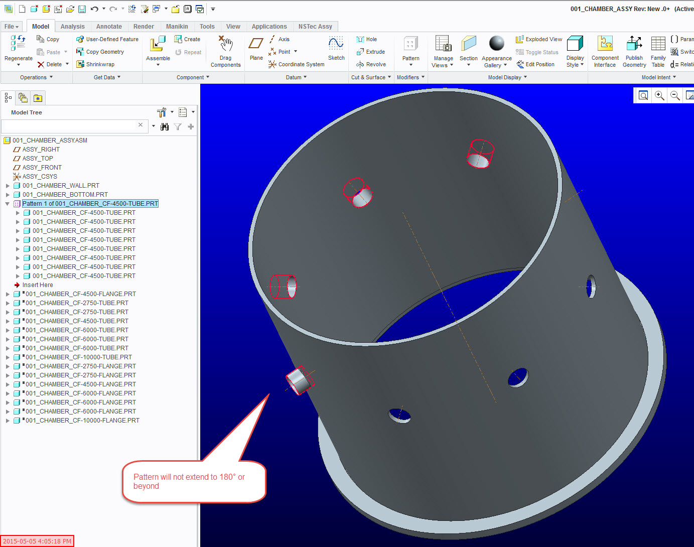
Seems easy enough...Model a cylinder. Create a radial hole by selecting outside of surface, offset 1, and angle offset. Pattern hole using angle offset. Open assembly. Assembly part to first hole (insert and orient to central axis so the reference doesn't stop rotation). Reference Pattern. Part will not pattern past 180°.
any ideas on how to fix this problem.
My goal is to have one set of patterned holes and on set of reference pattern assembly comps.
Ps...I tried using datum planes and that did not solve the problem.
Pss.I asked this question a while ago and even stumped PTC tech support. Pre CREO 2.0
Thanks,
Eric
Here are some images to help clarify.


This thread is inactive and closed by the PTC Community Management Team. If you would like to provide a reply and re-open this thread, please notify the moderator and reference the thread. You may also use "Start a topic" button to ask a new question. Please be sure to include what version of the PTC product you are using so another community member knowledgeable about your version may be able to assist.
- Labels:
-
Assembly Design
- Mark as New
- Bookmark
- Subscribe
- Mute
- Subscribe to RSS Feed
- Permalink
- Notify Moderator
I think the insert is causing trouble. Assumptions are made between the hidden world coordinate systems in the part and assembly that cause issues when rotating past 180 degrees. By creating the placement references in the cylinder part first, the smaller pieces can be correctly assembled via pattern.
Sample files are attached (WF5)
- Mark as New
- Bookmark
- Subscribe
- Mute
- Subscribe to RSS Feed
- Permalink
- Notify Moderator
When you made your holes, was it "Through All", or was it defined as "Through Next", "To Selected", or a blind depth? If it was a through all, there might be a problem with the cutout that is occurring where there is no material.
I have often had issues with patterning radially by manipulating an angle dimension. I often find that the "Axis Pattern" will not give up half-way through.
- Mark as New
- Bookmark
- Subscribe
- Mute
- Subscribe to RSS Feed
- Permalink
- Notify Moderator
In general I've found that the axial pattern option is more dependable than dimension based when creating these pattern types. Its the old case of all cylinder/circles are really two 180 degree halves. Rather than set the placement of the inserts by the cylinder surface you can dimension them from the center axis. You could also copy the two cylinder surfaces to create one new surface and reference that when assembling instead.


