
Turn on suggestions
Auto-suggest helps you quickly narrow down your search results by suggesting possible matches as you type.
Showing results for
Please log in to access translation
Turn on suggestions
Auto-suggest helps you quickly narrow down your search results by suggesting possible matches as you type.
Showing results for
- Community
- Creo+ and Creo Parametric
- 3D Part & Assembly Design
- Pattern relation question
Translate the entire conversation x
Please log in to access translation
Options
- Subscribe to RSS Feed
- Mark Topic as New
- Mark Topic as Read
- Float this Topic for Current User
- Bookmark
- Subscribe
- Mute
- Printer Friendly Page
Pattern relation question
Aug 01, 2014
11:35 AM
- Mark as New
- Bookmark
- Subscribe
- Mute
- Subscribe to RSS Feed
- Permalink
- Notify Moderator
Please log in to access translation
Aug 01, 2014
11:35 AM
Pattern relation question
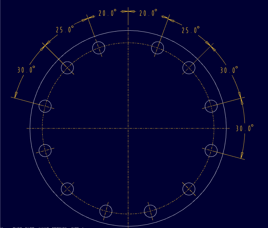
Trying to create my first patern relation and having a bit of a problem. I want to pattern a hole so that there are 12 instances total. The pattern will only be in one direction which is an angle. The first hole patterned I want it to be 25 degrees away from the first hole. The next 9 holes I want to be 30 degrees away from the 1st patterned hole. Then the last hole I want it to be 25 degrees away from the last hole. Please see the picture attached.
Now I know I could define each hole at a certain angle but I was wanting to do it a little more simpler. Below is what I have. But I don't think I fully understand how creo evaulates the relation which is why it isn't working.
increment1 = 0
if idx1 == 1 (first patterned hole, 25 degrees away from original hole)
memb_v = 25
endif
if idx1 >= 2 | idx1 <= 10 (patterned holes 2 through 10, 30 degress from each other)
memb_v = 30 + increment1
increment1 = 30 + increment1
endif
if idx1 == 11 (last hole patterened, 25 degrees away from last hole patterened)
memb_v = 25 - 30 + increment1
endif
So what I'm trying to do is use the "increment1" to keep increasing the angle by 30 degrees for patterened holes 2 though 10. And then the last hole only moves 25 degrees from the 2nd to last patterned hole.
"increment1" isn't defined as a paramenter. Not sure if this is necessary or not.
Any help is greatly appreciated!
This thread is inactive and closed by the PTC Community Management Team. If you would like to provide a reply and re-open this thread, please notify the moderator and reference the thread. You may also use "Start a topic" button to ask a new question. Please be sure to include what version of the PTC product you are using so another community member knowledgeable about your version may be able to assist.
Solved! Go to Solution.
Labels:
- Labels:
-
General
ACCEPTED SOLUTION
Accepted Solutions
Aug 04, 2014
02:01 PM
- Mark as New
- Bookmark
- Subscribe
- Mute
- Subscribe to RSS Feed
- Permalink
- Notify Moderator
Please log in to access translation
Aug 04, 2014
02:01 PM
Hi Wayne,
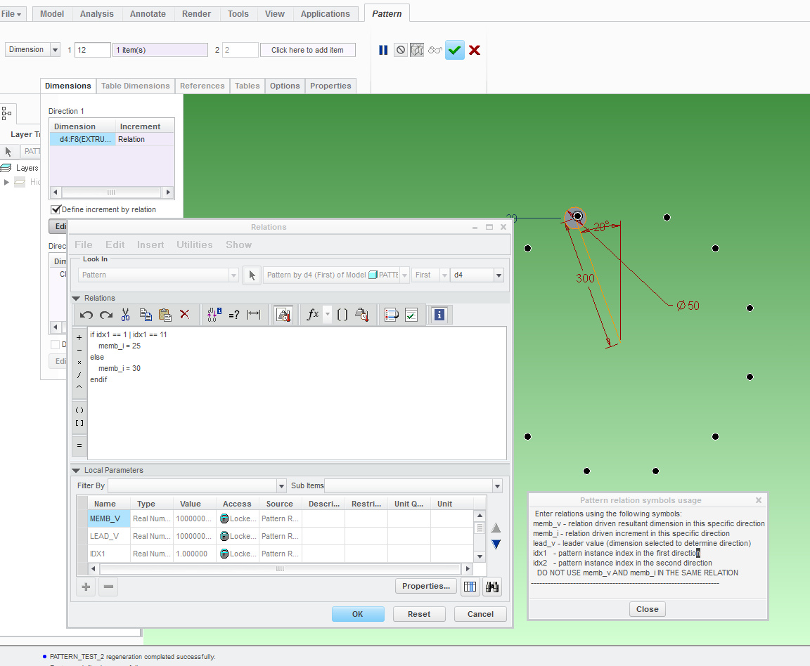
The relation above does what you are asking.
In the above example, the dimension that drives the pattern is d4 (20°). The pattern relation for it specifies that for the 1st and 11th instance, the increment (memb_i) should be 25°, and 30° for the others.
You were using the right logic but the system does not allow you to implement it - because it will not keep track of your increment1 variable. So use the prescribed memb_i variable OR expressions such as memb_v = lead_v + idx1*30 to achieve the kind of automation you seek.
Regards,
Paul
8 REPLIES 8
Aug 01, 2014
11:55 AM
- Mark as New
- Bookmark
- Subscribe
- Mute
- Subscribe to RSS Feed
- Permalink
- Notify Moderator
Please log in to access translation
Aug 01, 2014
11:55 AM
Atb this point, I settle for point patterns. I can sketch my desired results and let the datum points in the sketch drive the pattern. The only problem is trying to get a bolt circle display on the drawing. For that, I have to add in what -is- common in 2 separate patterns. There is no easy way to force a P.D. axis set in the drawing (circular axis).
Aug 02, 2014
07:14 PM
- Mark as New
- Bookmark
- Subscribe
- Mute
- Subscribe to RSS Feed
- Permalink
- Notify Moderator
Please log in to access translation
Aug 02, 2014
07:14 PM
Using datum points does make sense in this instance. Still would be nice to know how to make a complicated relation for this though.
Aug 02, 2014
07:54 PM
- Mark as New
- Bookmark
- Subscribe
- Mute
- Subscribe to RSS Feed
- Permalink
- Notify Moderator
Please log in to access translation
Aug 02, 2014
07:54 PM
The alternative is a pattern table. I am hoping this will solve the circular P.D. axis in the drawing.
I'll see what I can come up with.
Aug 02, 2014
08:11 PM
- Mark as New
- Bookmark
- Subscribe
- Mute
- Subscribe to RSS Feed
- Permalink
- Notify Moderator
Please log in to access translation
Aug 02, 2014
08:11 PM
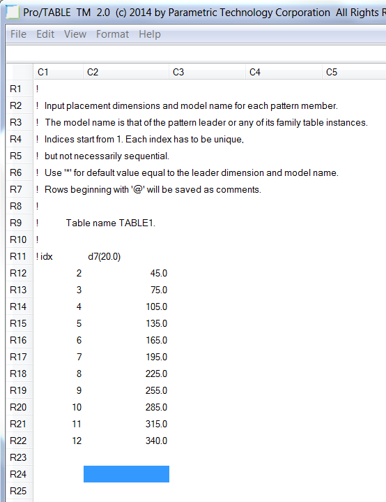
This is easier than 1st thought... note the values are base on the zero reference and therefore not cumulative.
Create the diameter hole references so you have an angle dim to put in the table (d7).
Enter the 1st new instance as the as an index and add to your heart's content.
This editor is right there in the table pattern type dialog.
And yes, the circular bolt pattern axis still works (that solves my issue! thanks  )
)
Aug 04, 2014
02:01 PM
- Mark as New
- Bookmark
- Subscribe
- Mute
- Subscribe to RSS Feed
- Permalink
- Notify Moderator
Please log in to access translation
Aug 04, 2014
02:01 PM
Hi Wayne,
The relation above does what you are asking.
In the above example, the dimension that drives the pattern is d4 (20°). The pattern relation for it specifies that for the 1st and 11th instance, the increment (memb_i) should be 25°, and 30° for the others.
You were using the right logic but the system does not allow you to implement it - because it will not keep track of your increment1 variable. So use the prescribed memb_i variable OR expressions such as memb_v = lead_v + idx1*30 to achieve the kind of automation you seek.
Regards,
Paul
Aug 04, 2014
02:23 PM
- Mark as New
- Bookmark
- Subscribe
- Mute
- Subscribe to RSS Feed
- Permalink
- Notify Moderator
Please log in to access translation
Aug 04, 2014
02:23 PM
Very nice, Paul. Never knew you could manipulae patterns in this way. Also learned about the -OR- state for IF statements. Missed that in Wayne's post but learned of it in studying Pro|Program this weekend.
I'll stick with the table for now, but this is very nice work!
Aug 04, 2014
03:57 PM
- Mark as New
- Bookmark
- Subscribe
- Mute
- Subscribe to RSS Feed
- Permalink
- Notify Moderator
Please log in to access translation
Aug 04, 2014
03:57 PM
Interesting that even though the value is in increments in your relation example, the value saved with the pattern is actually cumulative when you show the annotation.
I never knew how to use that relation button since is was usually grayed out (I use axis rotation a lot!).
Learn something new every day!
Thanks again!
Wayne, you might want to mark Paul's answer as correct.
Aug 04, 2014
06:11 PM
- Mark as New
- Bookmark
- Subscribe
- Mute
- Subscribe to RSS Feed
- Permalink
- Notify Moderator
Please log in to access translation
Aug 04, 2014
06:11 PM
Hi Antonious, it's good to hear that you learn something from me, because I sure learn a lot from you!
I guess it makes sense that the annotated dimensions show up as being "cumulative", since it seems that for each instance in the pattern, it is the leader's d4 dimension that is being cloned and changed by the system. I suppose what is provided in the pattern relations is the memb_i "shortcut". I was playing with the above example and succeeded with using the memb_v variable to get the same result - albeit it is more complicated:
if idx1 == 1
memb_v = lead_v + 25
else
if idx1 == 11
memb_v = lead_v + 25 + (idx1-1)*30 - 5
else
memb_v = lead_v + 25 + (idx1-1)*30
endif
endif


