Community Tip - Did you get called away in the middle of writing a post? Don't worry you can find your unfinished post later in the Drafts section of your profile page. X
- Community
- Creo+ and Creo Parametric
- 3D Part & Assembly Design
- Post Pocessing Modal Analysis (Line graph question...
- Subscribe to RSS Feed
- Mark Topic as New
- Mark Topic as Read
- Float this Topic for Current User
- Bookmark
- Subscribe
- Mute
- Printer Friendly Page
Post Pocessing Modal Analysis (Line graph question)?
- Mark as New
- Bookmark
- Subscribe
- Mute
- Subscribe to RSS Feed
- Permalink
- Notify Moderator
Post Pocessing Modal Analysis (Line graph question)?
Hello All
I've recently started using Mechanica (wildfire 4.0) for prelimanary analyses, instead of ANSYS. Just to verify results, I am running a modal analysis on a cylinder to get displacement distribution along the length of the cylinder.
I get results, and they match my calculations. Now I want to plot a displacement graph; Y-axis showing displacement, and X-axis showing length of cylinder. To get that, what I know, I need to define a line through or on the cylinder. I have tried making a sketch line, datum line, and even axis, through the center of cylinder, but Mechanica doesnt let me choose that line for graph. I guess because that line is not a part of cylinder, but an arbitrary sketch.
My question: Is there a way to do this? How can I get a line displacement plot along the length of cylinder?
Thanks!
Haris
This thread is inactive and closed by the PTC Community Management Team. If you would like to provide a reply and re-open this thread, please notify the moderator and reference the thread. You may also use "Start a topic" button to ask a new question. Please be sure to include what version of the PTC product you are using so another community member knowledgeable about your version may be able to assist.
- Labels:
-
General
- Mark as New
- Bookmark
- Subscribe
- Mute
- Subscribe to RSS Feed
- Permalink
- Notify Moderator
Haris:
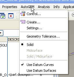
After you sketch the line in the model, you need to make the line a hard curve in Mechanica using the AutoGEM hard curve control. You should be able to plot along the line once you do that.
Eduardo
- Mark as New
- Bookmark
- Subscribe
- Mute
- Subscribe to RSS Feed
- Permalink
- Notify Moderator
Thanks for the reply Eduardo.
So this is what I did. I defined a sketch line in cylinder. Then
AutoGEM > Control > Edge Distribution (Selected line, and defined number of nodes).
Ran simulation, got results. After checking a specific mode, selected Graph in Display Type, and in Graph Location selected Curve. This time I was able to select that Hard line. After clickign Ok and Show, I get this error:
'None of the selected result windows can be shown'.
Where'd I mess up?
Haris
- Mark as New
- Bookmark
- Subscribe
- Mute
- Subscribe to RSS Feed
- Permalink
- Notify Moderator
Haris:
My mistake. I missed the fact that you were using WF4. The AutoGEM hard curve control wasn't available till WF5. At this point, I can't think of anything that you could do in WF4 that will serve your purpose. Sorry for the mistake.
Eduardo
- Mark as New
- Bookmark
- Subscribe
- Mute
- Subscribe to RSS Feed
- Permalink
- Notify Moderator
Try creating a volume region in Mechanica that splits your shaft along its axis into two equal volumes. You can then select the edge/curve created by this volume region as your plot curve. If you're working with a hollow shaft, you will have 4 curves that you can choose. If it is a solid shaft, you will have 2 curves.
- Mark as New
- Bookmark
- Subscribe
- Mute
- Subscribe to RSS Feed
- Permalink
- Notify Moderator
Yes, I already tried that. Increases solution time, and becomes more complicated in complex geometry. But you are right, this is the best solution so far.
Thanks
- Mark as New
- Bookmark
- Subscribe
- Mute
- Subscribe to RSS Feed
- Permalink
- Notify Moderator
I just figured this one out. You need to include the curve in the mesh via AutoGEM selection "Use Datum Curves"


