Community Tip - If community subscription notifications are filling up your inbox you can set up a daily digest and get all your notifications in a single email. X
- Community
- Creo+ and Creo Parametric
- 3D Part & Assembly Design
- Re: Problems blending a curve edge?
- Subscribe to RSS Feed
- Mark Topic as New
- Mark Topic as Read
- Float this Topic for Current User
- Bookmark
- Subscribe
- Mute
- Printer Friendly Page
Problems blending a curve edge?
- Mark as New
- Bookmark
- Subscribe
- Mute
- Subscribe to RSS Feed
- Permalink
- Notify Moderator
Problems blending a curve edge?

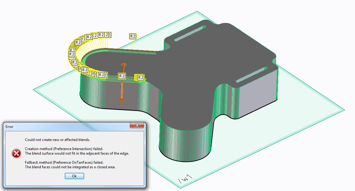
Hi, new to Creo, trying out creo elements direct express.
Whenever I try to apply a blend to the above edge I get this error:
"Could not create new or effected blends
Creation method (preference intersection) failed
The blend surface would not fit in the adjacent faces of the edge
Fallback method (preference ontanfaces failed)
The blend could not be integrated as a closed area"
any suggestions for a solution? Thanks
Solved! Go to Solution.
- Labels:
-
Surfacing
Accepted Solutions
- Mark as New
- Bookmark
- Subscribe
- Mute
- Subscribe to RSS Feed
- Permalink
- Notify Moderator
A rebuilt step file is attached.
Mind you, I made the best of what I saw in the file. Nothing was balanced but they overlay pretty well.
This is what a STEP file -should- look line when you import it ![]()
- Mark as New
- Bookmark
- Subscribe
- Mute
- Subscribe to RSS Feed
- Permalink
- Notify Moderator
Welcome to the forum, Crans.
What is the source of the original model? It looks like an imported facet model.
- Mark as New
- Bookmark
- Subscribe
- Mute
- Subscribe to RSS Feed
- Permalink
- Notify Moderator
The model you see was created by first importing a .step file into creo (a circuit board model exported from Diptrace) then a workplane was created on the PCB surface and the outline of the PCB projected onto the workplane, from there the outline of the surface was pulled to create a solid part. Then i tried to apply the blend tool to the edge and had problems. I am trying to create a 3d model of an enclosure for a PCB, which i will then 3d print. Thanks
the original PCB model file is eldis.step which i have posted with this message
- Mark as New
- Bookmark
- Subscribe
- Mute
- Subscribe to RSS Feed
- Permalink
- Notify Moderator
Yes, I can see that. This is a very poor import file. Even though it is STEP, it is actually a very crude DXF using polylines that is masquerading as a STEP. Even DXF should have created arcs but this one didn't. The only actual arcs in the file are the 4 small holes.
Can you get a more native version of the circuit board file? I'll see if I can recreate it with a little more intelligence.
- Mark as New
- Bookmark
- Subscribe
- Mute
- Subscribe to RSS Feed
- Permalink
- Notify Moderator
A rebuilt step file is attached.
Mind you, I made the best of what I saw in the file. Nothing was balanced but they overlay pretty well.
This is what a STEP file -should- look line when you import it ![]()
- Mark as New
- Bookmark
- Subscribe
- Mute
- Subscribe to RSS Feed
- Permalink
- Notify Moderator
Hi Antonius,
I tried the file you rebuilt and it blends perfectly, many thanks!![]()
I originally created the .dxf board outline in a 2d cad program then imported into diptrace pcb cad program.
I had problems with setting it as the board outline so i ended up tracing by hand over the original on one layer
to another layer (board outline layer) using segments, this is probably where my problem started. I will not do this in the future. How did you manage to rebuild? looks great.... thanks again
- Mark as New
- Bookmark
- Subscribe
- Mute
- Subscribe to RSS Feed
- Permalink
- Notify Moderator
I opened the board and created a sketch next to it.
I found some common references and rebuilt it based on what seemed logical in the design.
To get the rounds, I places circles on 3 vertices of each arc and rounded the radius.
It took a lot of assumptions but in the end, an overlay was the main confirmation. You might look at those 2 holes between the "rabbit ears". They are off-center by 0.1mm. They are 9mm apart, but 4.4mm to the right of the centerline.


