- Community
- Creo+ and Creo Parametric
- 3D Part & Assembly Design
- Re: Problems with Singularities; New to Simulate
- Subscribe to RSS Feed
- Mark Topic as New
- Mark Topic as Read
- Float this Topic for Current User
- Bookmark
- Subscribe
- Mute
- Printer Friendly Page
Problems with Singularities; New to Simulate
- Mark as New
- Bookmark
- Subscribe
- Mute
- Subscribe to RSS Feed
- Permalink
- Notify Moderator
Problems with Singularities; New to Simulate
All,
I am new to the world of FE analysis and I am trying to teach myself how to use Creo Simulate (aka Mechanica) so that I can begin to perform meaningful analysis on various parts/assemblies that I will be designing. With that being said, I am hoping you might be able to help me out.
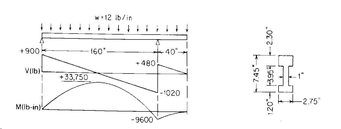
I wanted to perform my first analysis on a problem with a known closed form solution in order to compare results between the two. I chose to look at the probelm below with the beam being made out of steel.
Positive: I was able to constrain the model, apply the loads, mesh the model using AutoGEM controls, run an analysis, and look at my results.
Negative: My expected results appear that they are being overshadowed by the support reaction on the left hand side of the figure which is causing a singularity and extremely high stresses in this location. In short, when I view the results, the beam appears as one solid color because the stresses throughout the beam are significantly less than those located at the support reaction. I also recieve a warning message eluding to this also.
I did some reading on dealing with singularities and how you can implement an 'Isolate for Exclusion' AutoGEM control to address this type of issue but I was unable to make any progress when I tried to implement this. My beam still looks the same and the results are the same for all practical purposes.
Here is what I would like to know:
What do I need to do in order to resolve this issue and obtain meaningful results and graphs?
Any help would be appreciated. I have also attached my part file so you can take a look at my model and how I constrained and loaded everything.
This thread is inactive and closed by the PTC Community Management Team. If you would like to provide a reply and re-open this thread, please notify the moderator and reference the thread. You may also use "Start a topic" button to ask a new question. Please be sure to include what version of the PTC product you are using so another community member knowledgeable about your version may be able to assist.
- Mark as New
- Bookmark
- Subscribe
- Mute
- Subscribe to RSS Feed
- Permalink
- Notify Moderator
Hello, Mark,
I tried your file, but it does not work.
I did not understand what to serve your two blue line below the room.
These two features can not beings used to place constraints.
In your file is missing constraint to 40 inches.
Any questions, just for all, please always do you use English measures?, Maybe this is the Imperial system
Cordially.
Denis
- Mark as New
- Bookmark
- Subscribe
- Mute
- Subscribe to RSS Feed
- Permalink
- Notify Moderator
Bummer. Just did a long post... but it didn't "take". Here's a truncated version.
Poisson's ratio wants to expand or contract the cross-section at your fixed constraint... but the fixed constraint won't let it. Your results are pretty accurate if the beam end is welded to a metal structure (less compliance in the "wall").
Plotting stresses along curves in your 3D model are accurate once you get away from the "local affect" of that constraint.
The nature of the math used for beam elements (a curve) is such that you'd match the closed form answers exactly. You can still plot graphs of the stress along the length of the curve for any recover point of interest (you can define up to 8 recovery points for a cross-section if you define your own cross-section).
Cheers.
- Mark as New
- Bookmark
- Subscribe
- Mute
- Subscribe to RSS Feed
- Permalink
- Notify Moderator
Hi Chauncey,
Thanks for the reply. What you've explained definitely makes sense.
In the ideal case, I'd like to not have to constrain in all 3 directions at the left constraint. However, if I try to do this I encounter a failure stating that the model is insufficiently constrained.
I was hoping that by including an 'isolate for exclusion' AutoGEM control' I could get Mechanica/Simulate to forget about this area and report stress maximums at the area of peak moment but I didn't have any luck with this. I think the moral of this story is that using the beam tool would likely be the best way to analyze this particular probelm. Thanks again for the help.


