
Turn on suggestions
Auto-suggest helps you quickly narrow down your search results by suggesting possible matches as you type.
Showing results for
Please log in to access translation
Turn on suggestions
Auto-suggest helps you quickly narrow down your search results by suggesting possible matches as you type.
Showing results for
Community Tip - Need to share some code when posting a question or reply? Make sure to use the "Insert code sample" menu option. Learn more! X
- Community
- Creo+ and Creo Parametric
- 3D Part & Assembly Design
- Project Lightning Wish List
Translate the entire conversation x
Please log in to access translation
Options
- Subscribe to RSS Feed
- Mark Topic as New
- Mark Topic as Read
- Float this Topic for Current User
- Bookmark
- Subscribe
- Mute
- Printer Friendly Page
Project Lightning Wish List
Sep 07, 2010
11:32 AM
- Mark as New
- Bookmark
- Subscribe
- Mute
- Subscribe to RSS Feed
- Permalink
- Notify Moderator
Please log in to access translation
Sep 07, 2010
11:32 AM
Project Lightning Wish List
This list is to articulate our wants and needs to PTC on what changes we would like to see to Pro/Engineer Wildfire with the release of Project Lightning. I was asked to put a list of what my company wanted to see in Lightning, and thought it would be better if PTC saw what the whole Pro/E community wanted to see.
Please keep all comment upbeat and positive. Absolutely no hate statements.
I think it is important to have some rules for this, so here is a starter on them. They are subject to change if it proves to be needed.
- One enhancement per reply - this will make it so people can comment directly to that request with additions, elaborations or +1, -1 comments
- Keep the requests specific and precise - consistent UI throughout Pro/E is a great request, but is very broad and might be better stated differently
- No mention of other company branding, names or abbreviations - if you want your request to be listened to don't say Pro/E needs to be like a different tool. I am sure you can find another way of stating or explaining your wish then make it like ..... Siting other PTC products is OK.
- No off topic discussions
- Keep all comments related to the request you are replying to
- When you post a new request, reply to the original post. This will keep all the request at the top level and better to read.
- Add pictures, screenshot, PDF's or other illustrations to help you point.
- Change the title of your post to have a short title for your request.
- Try to make your request fit with WF5 where possible. It would be useless to request something they already did in WF5. (for example: Update the Cabling module)
- The list is not in order of importance. You can put any request in any order.
- etc...
I will start with a couple requests to get the ball rolling. I will keep adding them over time to give opportunity for others to add requests.
This thread is inactive and closed by the PTC Community Management Team. If you would like to provide a reply and re-open this thread, please notify the moderator and reference the thread. You may also use "Start a topic" button to ask a new question. Please be sure to include what version of the PTC product you are using so another community member knowledgeable about your version may be able to assist.
Labels:
- Labels:
-
Data Exchange
82 REPLIES 82
Sep 10, 2010
12:51 AM
- Mark as New
- Bookmark
- Subscribe
- Mute
- Subscribe to RSS Feed
- Permalink
- Notify Moderator
Please log in to access translation
Sep 10, 2010
12:51 AM
Hi Paul,
Now that I have seen this I will add the other ideas (mostly interface) to discussion rather than individual random posts.
Regards, Brent
Sep 10, 2010
10:12 AM
- Mark as New
- Bookmark
- Subscribe
- Mute
- Subscribe to RSS Feed
- Permalink
- Notify Moderator
Please log in to access translation
Sep 10, 2010
10:12 AM
Ok, you had some good ideas in the other posts. I guess I thought it might be better to have them grouped. That way they don't get lost, and don't clog up the system.
Sep 10, 2010
02:58 PM
- Mark as New
- Bookmark
- Subscribe
- Mute
- Subscribe to RSS Feed
- Permalink
- Notify Moderator
Please log in to access translation
Sep 10, 2010
02:58 PM
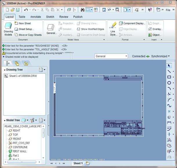
Update the drawing capabilities to be equal to what they are in Sketcher mode. Sometimes there is a need to create just 2D drawings for a quick display, plant layouts, flat flexible circuits, etc.
Currently in Drawing mode you are extremely limited on what you can do, and what you can do is very hard to figure out and remember.
Here is a pieced together screenshot of what I would like to see:
Oct 01, 2010
11:18 AM
- Mark as New
- Bookmark
- Subscribe
- Mute
- Subscribe to RSS Feed
- Permalink
- Notify Moderator
Please log in to access translation
Oct 01, 2010
11:18 AM
I like the idea of a draft sketch feature in the modeling environment. Same as a sketch feature but with the "option" of no constraints or external "to the sketch" references. Also included would be a few traditional 2D manipulation commands. And hopefully it is not packaged up in a separately priced module.
Joe
Sep 10, 2010
03:14 PM
- Mark as New
- Bookmark
- Subscribe
- Mute
- Subscribe to RSS Feed
- Permalink
- Notify Moderator
Please log in to access translation
Sep 10, 2010
03:14 PM
There are many things I really like about the measuring capabilities in Pro/E. I love it that you can set the first attachment and then just click to add and change the second attachment. Then, Pro/E automatically gives you the distance between value. I like it that you can select the radius tool and then just click on rounds and see what the diameter is.
But there are some things I would like better.
It would be nice if dimensioning was all done in one dashboard control. After clicking the measure icon a dashboard came up and I could select which type of measurement I wanted, or Pro/E would just know from the selections I make.
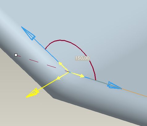
I also have a really hard time with the angle measurement. Usually I want to know the angle between two surfaces. So, I pick those surfaces. Pro/E then gives me the angle that I would not have even thought of wanting.
Here is a quick screenshot example:
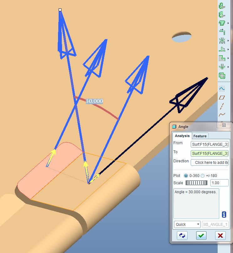
I then have to click on arrows till I get the angle to switch around to display what I hope is right. You never can get it to give you the actual angle between faces.
Here I found the correct angle, but why is it shifted 90 degrees?
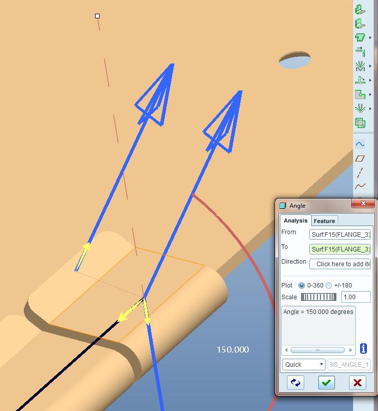
This is an easy angle to calculate, but it shows the point.
Sep 10, 2010
08:04 PM
- Mark as New
- Bookmark
- Subscribe
- Mute
- Subscribe to RSS Feed
- Permalink
- Notify Moderator
Please log in to access translation
Sep 10, 2010
08:04 PM
It measures the angle between the normal vectors of the surfaces. By default ProE uses the outward pointing normal for solid surfaces. Two of the arrows control the direction of the normals the other controls how the angle is measured according to the right hand rule. From your measurement you picked the horizontal surface first then the angled. Having the normal for the horizontal surface pointed up and moving the angled surface normal so they have the same origin the angle is measured clockwise (+) by right hand rule. If you flip the yellow arrow normal to both surface normals you measure counterclockwise and get -330. If you flip the horizontal surface normal direction you now measure counter clockwise (+) and get 150. If you flip the yellow arrow normal to both surface normals you measure clockwise and get -210.
The easiest way to see why the angle you initially get is wrong is to look at how the normals get oriented with a protractor in mind. So think of a protractor measureing the angle with 0 along the horizontal surface and 150 on the angled surface. Extend arrows in the 0 and 150 directions. Now rotate them 90 degrees counter clockwise to see how they should be oriented to get the correct measurement. Notice in your picture, if you left the horizontal normal pointing up, the angled normal would point in the wrong direction because from the protractor example the normal is rotated 90 degrees clockwise. So on a protractor with the arrows moved to the origin you have the horizontal normal arrow lined up with 90 and the angled normal arrow lined up with 60 (angle between them is 30). When you flip the direction of one of the surface normals you then get the correct angle measurement.
Sep 12, 2010
01:58 PM
- Mark as New
- Bookmark
- Subscribe
- Mute
- Subscribe to RSS Feed
- Permalink
- Notify Moderator
Please log in to access translation
Sep 12, 2010
01:58 PM
That is a great explanation. But I still think it would be much easier to figure out if it just gave you arrows like my hacked up example below. I shouldn't have to hold my right hand up to the monitor and hum and ha about it. I don't use a protractor I use Pro/E. I never learned how to draw 3D. I expect Pro/E to do that for me. Then tell me what I want to know. 
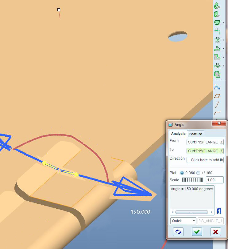
Then, you could see the twol surfaces you selected and tell what way Pro/E is looking at it and know the angle you wanted first.
I would love it.
Sep 14, 2010
04:22 PM
- Mark as New
- Bookmark
- Subscribe
- Mute
- Subscribe to RSS Feed
- Permalink
- Notify Moderator
Please log in to access translation
Sep 14, 2010
04:22 PM
The problem comes about becaues you're measuring the angle in three dimensional space not two dimensional. If you want to get the arrows as you have shown use the edges of surfaces for the measurement references. You may still need to flip a direction for an arrow but it will be in the form you desire.
Oct 04, 2010
10:10 AM
- Mark as New
- Bookmark
- Subscribe
- Mute
- Subscribe to RSS Feed
- Permalink
- Notify Moderator
Please log in to access translation
Oct 04, 2010
10:10 AM
Thanks Kevin, measuring angles at the edges works mostly how I thought selecting the planes would. Would be nice is the default angle was between the two edges selected, but I can handle one arrow swap, I guess
Sep 10, 2010
06:07 PM
- Mark as New
- Bookmark
- Subscribe
- Mute
- Subscribe to RSS Feed
- Permalink
- Notify Moderator
Please log in to access translation
Sep 10, 2010
06:07 PM
Section with Ease
Almost always if you do a section it removes the bit furtherist away from you and you have to spin the model 180deg
ProE is littered with poor interface features - even in the latest stuff, Appearance Manager for example, its not good. PTC need to change their whole process of designing these things otherwise Project Lightning will deliver more of the same.
Sep 10, 2010
06:38 PM
- Mark as New
- Bookmark
- Subscribe
- Mute
- Subscribe to RSS Feed
- Permalink
- Notify Moderator
Please log in to access translation
Sep 10, 2010
06:38 PM
Appearance Manager (WF5)
How do you select SOLID SURFACES in WF5 within the Appearance Mngr tool ? Its not on right button.
To do this now you have to do it before using the tool. 
Sep 12, 2010
01:13 PM
- Mark as New
- Bookmark
- Subscribe
- Mute
- Subscribe to RSS Feed
- Permalink
- Notify Moderator
Please log in to access translation
Sep 12, 2010
01:13 PM
Just thought of this one while trying to add a new part to an assembly.
I think it would be nice to be able to only show the datum of of the part in the assembly that you are working on. Then, also turn on daums of other specific parts or maybe the top assembly.
Sometimes it gets so hard to see what datum you are trying to click.
For example: I want to build a new part that fits between the purple and red tubes. I want to build it using the internal part datums.
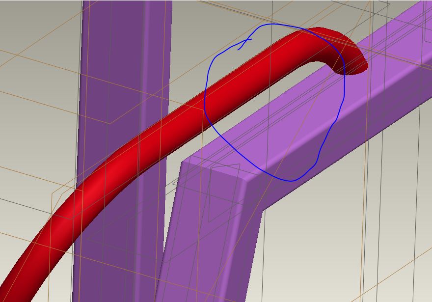
I know that picture is too small to show everything. But it does show lots of datums.
Sep 28, 2010
04:37 PM
- Mark as New
- Bookmark
- Subscribe
- Mute
- Subscribe to RSS Feed
- Permalink
- Notify Moderator
Please log in to access translation
Sep 28, 2010
04:37 PM
Yes, it would be great to have more options to show or hide datums during you are adding a new part to the assembly.
Sep 12, 2010
02:05 PM
- Mark as New
- Bookmark
- Subscribe
- Mute
- Subscribe to RSS Feed
- Permalink
- Notify Moderator
Please log in to access translation
Sep 12, 2010
02:05 PM
@David Butz, I agree with you about the "endmill cutting" feature I would love that! Do you know how powerful that would be, wrapping a "endmill" cut around a cylinder, as one of your example shows.
Sep 13, 2010
11:00 AM
- Mark as New
- Bookmark
- Subscribe
- Mute
- Subscribe to RSS Feed
- Permalink
- Notify Moderator
Please log in to access translation
Sep 13, 2010
11:00 AM
Is anybody listening? There was a response from a PTC manager to one of Brent's earlier posts concerning the enhancement process; we were told that it is a work in progress. That's fine, and I hope the result will be worthwhile. Meanwhile, it would be nice to know whether or not we are wasting our time in this thread. Could someone at PTC please let us know if this discussion is at least being scanned? There is no anger or sarcasm implied; it's a simple request.
Sep 13, 2010
01:42 PM
- Mark as New
- Bookmark
- Subscribe
- Mute
- Subscribe to RSS Feed
- Permalink
- Notify Moderator
Please log in to access translation
Sep 13, 2010
01:42 PM
Hello Everybody,
I guess it will be premature for us to imgine how Project Lightning is going to shape up/work. I can still wish that PTC
may please incorporate some new features as I wished in my earlier post either in Pro/E or Project Lightning. I am adding more today.
(1) TWO WAY ASSOCIATIVITY FOR MERGE PART. THIS WILL HELP IN CASTING TO MACHINING OF THE PART.
(2) ALSO WHEN THE SKELETON IS USED, PART DIMESIONS CAN BE DETAILED WITH REAL DIMENSIONS NOT REFERENCE DIMENSIONS.
(3) INTER ACTIVE SURFACE DESIGN CAN BE ENHANCED TO BE SIMBLE LIKE AUTODESK STUDIO TOOLS WITH ACTUAL DIMENSIONS.
(4) CO-CREATE SHOULD BE LINKED TO PRO/E EITHER AS ADDITION FEATURE OR MODULE.
(5) ALL LOYAL LONG TIME USERS CAN BUY THAT AT REASONALBE PRICE WITH NO ADDITIONAL MAINTENACE COST FOR LICENSE
EVERY YEAR.
(6) AS SOON AS THE PROJECT LIGHTNING IS AVAILABLE, PRECISON LEARNING SHOULD HAVE WEB BASE TRAINING AVAILABLE
NOT AFTER TWO OR THREE YEARS.
(7) LAST WISH FOR TODAY, THE KIND, RESPONSIBLE AND VERY RENSPONSIVE PERSONNEL FROM PTC SHOULD LOOK INTO EACH POST
EVERYDAY AND RESPOND TO THE DISCUSSION WITH SOME KIND OF FEED BACK TO THE PARTICIPANTS.
Thanks.
Gautam Vora.
Sep 13, 2010
04:00 PM
- Mark as New
- Bookmark
- Subscribe
- Mute
- Subscribe to RSS Feed
- Permalink
- Notify Moderator
Please log in to access translation
Sep 13, 2010
04:00 PM
let me start off saying that I know all about simplified reps.
In an assembly, what I would like is to be able to ctrl-click on several parts and then right click and say "hide all others"
This would let me isolate the few parts I'm interested in and check fit / interferances or just assemble the parts together.
It's the only thing that gives me any kind of envy for other cad programs.
Sep 28, 2010
10:28 AM
- Mark as New
- Bookmark
- Subscribe
- Mute
- Subscribe to RSS Feed
- Permalink
- Notify Moderator
Please log in to access translation
Sep 28, 2010
10:28 AM
Product development and upgrade path. I want the new functionality in the latest WC, but don't need anything of the latest in WF, however a bump up in PV would be helpful, but not the latest buggy one. Oh you mean I have to get the latest in all of the above to get one? That's not very convenient! How about taking the time to make the products a little more downward compatible?
Sep 28, 2010
04:52 PM
- Mark as New
- Bookmark
- Subscribe
- Mute
- Subscribe to RSS Feed
- Permalink
- Notify Moderator
Please log in to access translation
Sep 28, 2010
04:52 PM
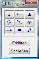
Maybe is ist possible to preselect on of the nine conditions in sketch mode. Even if the preselection ist not the one you like to use. There is a 1/9 chance that the preselection is the right one.
I use the condition feature more then 100 times a day and in 80% i choose the point to point condition. I think the improvement can save a lot of clicks.
Oct 03, 2010
09:16 PM
- Mark as New
- Bookmark
- Subscribe
- Mute
- Subscribe to RSS Feed
- Permalink
- Notify Moderator
Please log in to access translation
Oct 03, 2010
09:16 PM
Hi Mathias,
I am wondering if you are on WF5? What I see on that is what you seem to be asking for. In WF5 once you use one constraint condition icons that becomes the default until you pick another one. The slight downside of this the "new" method compared to WF4 is the the current constraint shows in the icon in the toolbar so I tend to do a double take if I am heading to the toolbar (especially if I am thinking of another constraint).
However the thing ion WF5 that means I don't use the toolbar so much is using the object action method in the Sketcher to select the two (or more) lines or points or whatever then using the Right Mouse button to select a constraint. I still have to remember to do this though.
I would say from my point of view that what you are asking for already exists in WF5. Hope this helps.
Regards,. Brent.
Oct 04, 2010
01:54 AM
- Mark as New
- Bookmark
- Subscribe
- Mute
- Subscribe to RSS Feed
- Permalink
- Notify Moderator
Please log in to access translation
Oct 04, 2010
01:54 AM
Hi Brent,
you are right, we are still using WF4.
I'm glad to hear about the improvement in sketcher mode at WF5.
Thank you for your answer.
Regards, Matthias.
Sep 30, 2010
08:50 AM
- Mark as New
- Bookmark
- Subscribe
- Mute
- Subscribe to RSS Feed
- Permalink
- Notify Moderator
Please log in to access translation
Sep 30, 2010
08:50 AM
Hi Everyone,
I just wanted to assure you that we are listening. I browse these pages fairly often. Many of the items in this wish-list discussion are familiar issues that would certainly be targets for improvement in future releases.
Keep the great ideas coming!
Brian
Oct 02, 2010
11:04 AM
- Mark as New
- Bookmark
- Subscribe
- Mute
- Subscribe to RSS Feed
- Permalink
- Notify Moderator
Please log in to access translation
Oct 02, 2010
11:04 AM
To,
Brian Thompson,
Gentleman,
I am bit surprised to read your statement. I am 10% happy to hear some 1% positive responses from behind the wall of the secretive PTC castle.
PTC is too slow to incorporate for adopting changes/adding new features in comparison to PTC competitors and this slowness makes PTC
loose new market share as well as current customers, I am going to give what I experience about 1-1/2 month ago. I was calling for
co-create technical support. My call went to the license renewal department. I talked to Meg in the same department regarding upgrading
my Pro/E seat license . She said that she would have the sale department call me. The sale person called me after about 1 hour. I asked
for quotation to upgrade my Pro/E license and send me the quotation by fax. Till this date, nobody has sent me that quotation. I wonder
that if that sale person has still job with PTC and if there is any superior to that sale person for the accountability of that sale person.
Also PTC is trying to develop so many software & products, (trying to be Jack of all but master of none).
I hope that I am not too harsh. I am just airing my opinion and frustration about PTC. If PTC feel I am harsh, I apologize in advance.
Thanks.
Gautam Vora.
Oct 03, 2010
08:01 AM
- Mark as New
- Bookmark
- Subscribe
- Mute
- Subscribe to RSS Feed
- Permalink
- Notify Moderator
Please log in to access translation
Oct 03, 2010
08:01 AM
A usable Feature Recognition Tool. One that can make an editable part from for instance a Step-file or even better from a point cloud or Stl-file.
Oct 04, 2010
10:15 AM
- Mark as New
- Bookmark
- Subscribe
- Mute
- Subscribe to RSS Feed
- Permalink
- Notify Moderator
Please log in to access translation
Oct 04, 2010
10:15 AM
That would be so helpful. I am sure it would be very hard to figure out. I don't think it would have to be completely automated, it could require user feedback. Maybe let the user adjust the order of operations. It would be nice if it didn't end up with all the removes and just had the new geometry.
Oct 04, 2010
10:20 AM
- Mark as New
- Bookmark
- Subscribe
- Mute
- Subscribe to RSS Feed
- Permalink
- Notify Moderator
Please log in to access translation
Oct 04, 2010
10:20 AM
No more old style menus. Pro-E Wildfire 5 still have old style menus in cross sections, sheetmetal, pro-welding, elicoidal sweep, blend, sweep and ather features. In this manner Pro-E appear old and not friendly.
By.
Oct 11, 2010
08:22 PM
- Mark as New
- Bookmark
- Subscribe
- Mute
- Subscribe to RSS Feed
- Permalink
- Notify Moderator
Please log in to access translation
Oct 11, 2010
08:22 PM
Well this was promised for Wildfire and we're now on version 5 and its still not complete.
Even the new stuff -drawing for example- is full of them. Try explaining the menu
systems to a newby you're training - the lack of action on this is appalling.
Repeat regions in drawings is another.
PTC should put some code into ProE so that every time the Menu manager comes up it sends
an email to the manager who's mismanaged this - whoever thinks this is OK in PTC needs to exit.
Oct 04, 2010
10:23 AM
- Mark as New
- Bookmark
- Subscribe
- Mute
- Subscribe to RSS Feed
- Permalink
- Notify Moderator
Please log in to access translation
Oct 04, 2010
10:23 AM
It would be really nice if PTC incorporated an integrated workflow in to Pro/E that included things like FEA, Mold Flow, Tolerance analysis, Mechanism analysis, manikin and other things. Pro/E should work in such a way that all models are inherently setup so that Mechanica works with out geometry errors. If WF6 will have a ribbon setup, the ribbon should have analysis built into it. The analysis tab would have the functionality available on it.
Oct 04, 2010
10:25 AM
- Mark as New
- Bookmark
- Subscribe
- Mute
- Subscribe to RSS Feed
- Permalink
- Notify Moderator
Please log in to access translation
Oct 04, 2010
10:25 AM
In the Sketch: rectangle by the center.
Now I often create 2 axes and than I create a simmetric rectangle, it will be helpfull a feature that create this three things with two click, one for the center and one for diagonal (like in solidworks).
Oct 05, 2010
07:27 AM
- Mark as New
- Bookmark
- Subscribe
- Mute
- Subscribe to RSS Feed
- Permalink
- Notify Moderator
Please log in to access translation
Oct 05, 2010
07:27 AM
I totaly agree with you Francesco.
It should be possible to make an entity symetric to any other line or reference line.


