Community Tip - You can Bookmark boards, posts or articles that you'd like to access again easily! X
- Community
- Creo+ and Creo Parametric
- 3D Part & Assembly Design
- Re: Projected Reference Points in Creo Parametric ...
- Subscribe to RSS Feed
- Mark Topic as New
- Mark Topic as Read
- Float this Topic for Current User
- Bookmark
- Subscribe
- Mute
- Printer Friendly Page
Projected Reference Points in Creo Parametric 2.0
- Mark as New
- Bookmark
- Subscribe
- Mute
- Subscribe to RSS Feed
- Permalink
- Notify Moderator
Projected Reference Points in Creo Parametric 2.0
Is it possible to create projected reference points in Creo Parametric 2.0? If so, how can it be done?
This functionality is present in Creo Elements/Direct Drafting 17. See: http://www.ptc.com/appserver/wcms/relnotes/note.jsp?&im_dbkey=105261

This thread is inactive and closed by the PTC Community Management Team. If you would like to provide a reply and re-open this thread, please notify the moderator and reference the thread. You may also use "Start a topic" button to ask a new question. Please be sure to include what version of the PTC product you are using so another community member knowledgeable about your version may be able to assist.
Solved! Go to Solution.
- Labels:
-
2D Drawing
Accepted Solutions
- Mark as New
- Bookmark
- Subscribe
- Mute
- Subscribe to RSS Feed
- Permalink
- Notify Moderator
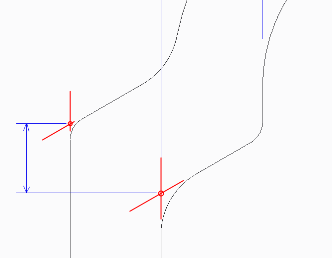
There is actually an option to draw those intersecting lines on the drawing. Not sure at the moment what it is called.
As for doing this in the model sketch, you can use the fillet feature in the sketch and it will create and constrain the construction lines for you. You can dimension to these lines as well in the sketch.
- Mark as New
- Bookmark
- Subscribe
- Mute
- Subscribe to RSS Feed
- Permalink
- Notify Moderator
Welcome to the forum, Mike.
In this case, the use of construction circles can help you obtain the desired constraints.
The use of points on intersections can also help.
Note on points, coordinate systems and axes in sketches: These references on the left side of the sketcher dialog are datum features and will persist after the sketch is saved. The ones on the right are reference features only available for the active sketch.
- Mark as New
- Bookmark
- Subscribe
- Mute
- Subscribe to RSS Feed
- Permalink
- Notify Moderator
So in the case of non-perpendicular lines with a round (forgive the crude drawing), I'd need to use construction lines that are made coincident to the geometry and then put a point at their intersection (ie; the red lines)? This would be done in the model, and would transfer over to the drawing to be dimensioned, correct?

- Mark as New
- Bookmark
- Subscribe
- Mute
- Subscribe to RSS Feed
- Permalink
- Notify Moderator
There is actually an option to draw those intersecting lines on the drawing. Not sure at the moment what it is called.
As for doing this in the model sketch, you can use the fillet feature in the sketch and it will create and constrain the construction lines for you. You can dimension to these lines as well in the sketch.


