
Turn on suggestions
Auto-suggest helps you quickly narrow down your search results by suggesting possible matches as you type.
Showing results for
Please log in to access translation
Turn on suggestions
Auto-suggest helps you quickly narrow down your search results by suggesting possible matches as you type.
Showing results for
Community Tip - Have a PTC product question you need answered fast? Chances are someone has asked it before. Learn about the community search. X
- Community
- Creo+ and Creo Parametric
- 3D Part & Assembly Design
- Re: Question regarding shell
Translate the entire conversation x
Please log in to access translation
Options
- Subscribe to RSS Feed
- Mark Topic as New
- Mark Topic as Read
- Float this Topic for Current User
- Bookmark
- Subscribe
- Mute
- Printer Friendly Page
Question regarding shell
Aug 24, 2023
03:28 PM
- Mark as New
- Bookmark
- Subscribe
- Mute
- Subscribe to RSS Feed
- Permalink
- Notify Moderator
Please log in to access translation
Aug 24, 2023
03:28 PM
Question regarding shell
Hello,
I am trying to recreate this model from solidworks modelmania 2013. (https://blogs.solidworks.com/tech/wp-content/uploads/sites/4/Model-Mania-2013-Phase-1-Drawing.jpg)
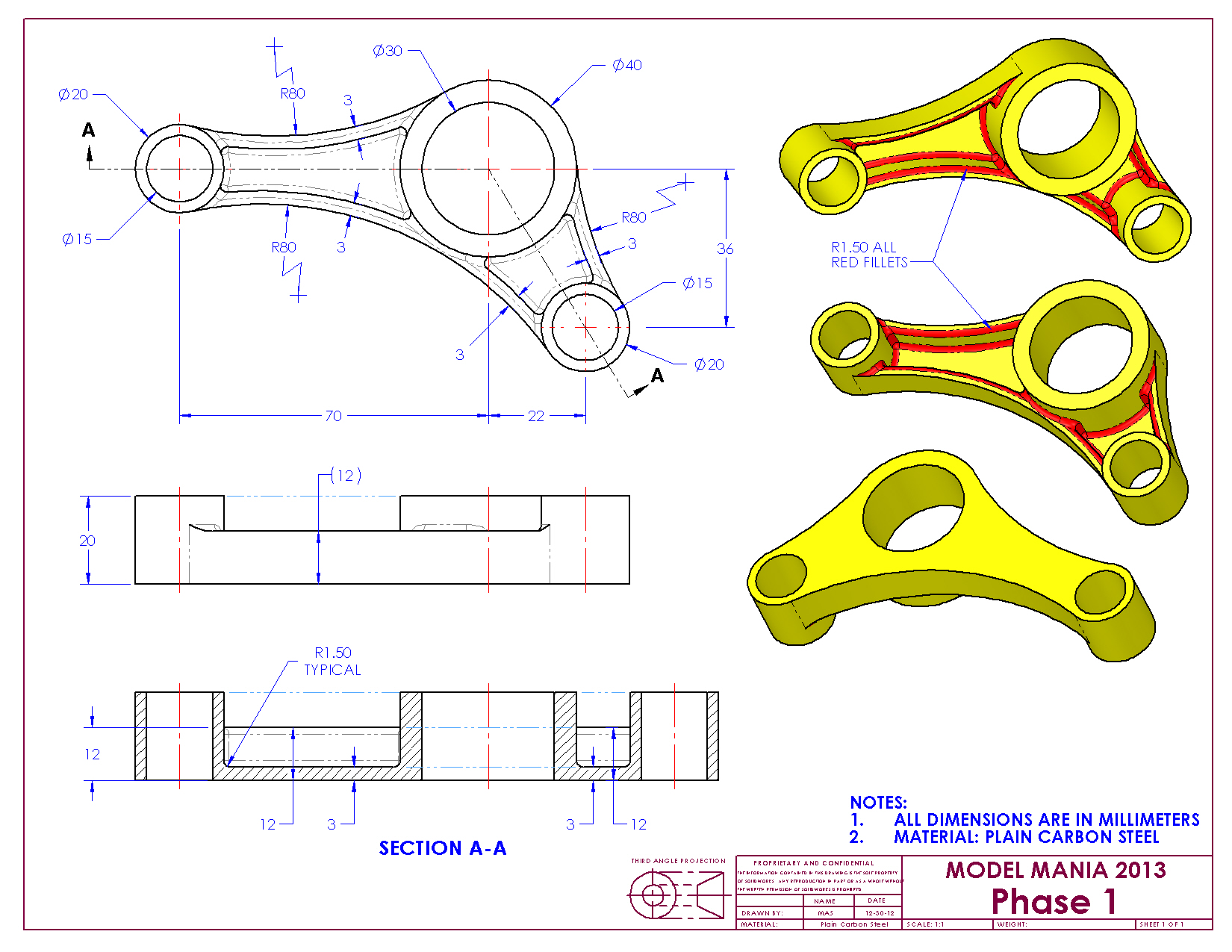
I thought about using the shell feature for the offset walls of value '3' circled below.

I believe I would be able to do this by using the shell, exclude surface feature however I was unable to do that; and it does make sense since the surface is not extended down into the other surface.

In the end I decided to use non-default thickness and it worked fine.

I wanted to ask how you would approach this? As always I really appreciate all your help.
Using Creo 9.0
Solved! Go to Solution.
Labels:
- Labels:
-
General
ACCEPTED SOLUTION
Accepted Solutions
Aug 25, 2023
04:00 AM
- Mark as New
- Bookmark
- Subscribe
- Mute
- Subscribe to RSS Feed
- Permalink
- Notify Moderator
Please log in to access translation
Aug 25, 2023
04:00 AM
If you're on Creo 7 or later, this sounds like a job for multibody modeling. Make the cylinders and the connecting parts as separate bodies. Here's a quick demo:
- Make a master sketch containing the three circles and the tangent lines.
- Use Sketch Regions to extrude the entire sketch (including the cylinders) to the base thickness.
- Extrude only the three circles, using Sketch Regions, as a separate body.
- Shell the main body.
- Subtract the cylinder body from the main body, while keeping both (so don't remove the cylinder body).
- Shell the cylinder body.
- Merge the two bodies together.
If you don't like using sketch regions (to be honest, I don't), you could do the same thing by just constraining the cylinder extrude to the first extrude sketch. That's probably better, to be honest. Fewer references that risk breaking.

18 REPLIES 18
Aug 24, 2023
03:34 PM
- Mark as New
- Bookmark
- Subscribe
- Mute
- Subscribe to RSS Feed
- Permalink
- Notify Moderator
Please log in to access translation
Aug 24, 2023
03:34 PM
Another method would be:
Create the "floor" 3 mm thick shape and then use thin option extrusion for the 3mm vertical walls on the perimeter of the floor by projecting the loop of the floor perimeter. This will give you the pockets that the shell yields.
========================================
Involute Development, LLC
Consulting Engineers
Specialists in Creo Parametric
Involute Development, LLC
Consulting Engineers
Specialists in Creo Parametric
Aug 24, 2023
04:01 PM
- Mark as New
- Bookmark
- Subscribe
- Mute
- Subscribe to RSS Feed
- Permalink
- Notify Moderator
Please log in to access translation
Aug 24, 2023
04:01 PM
I tried doing that but I can't for some reason any idea what the problem might be?
The sketch.

Extruding as a surface or solid works.


But thicken sketch doesn't work I suspect it due to the corners being too close.

Aug 24, 2023
04:07 PM
- Mark as New
- Bookmark
- Subscribe
- Mute
- Subscribe to RSS Feed
- Permalink
- Notify Moderator
Please log in to access translation
Aug 24, 2023
04:07 PM
Create the shape in the top view. Then raise the walls around the perimeter. Refer to the video as a guide.
========================================
Involute Development, LLC
Consulting Engineers
Specialists in Creo Parametric
Involute Development, LLC
Consulting Engineers
Specialists in Creo Parametric
Aug 24, 2023
04:47 PM
- Mark as New
- Bookmark
- Subscribe
- Mute
- Subscribe to RSS Feed
- Permalink
- Notify Moderator
Please log in to access translation
Aug 24, 2023
04:47 PM
Ah okay I understand now, I was trying to create the thicken sketch after extruding the cylinders and that does not work. Thickening the perimeter and then creating the cylinders works perfectly. So I was messing up the order in which to do it resulting in the error. I definitely prefer your method over mine thanks a lot.
Aug 24, 2023
04:48 PM
- Mark as New
- Bookmark
- Subscribe
- Mute
- Subscribe to RSS Feed
- Permalink
- Notify Moderator
Please log in to access translation
Aug 24, 2023
04:48 PM
Disregard the video, I forgot to remove it after realising my error.
Aug 24, 2023
04:06 PM
- Mark as New
- Bookmark
- Subscribe
- Mute
- Subscribe to RSS Feed
- Permalink
- Notify Moderator
Please log in to access translation
Aug 24, 2023
04:06 PM
The second phase of this challenge is as following. The main difference being there's is a partial "shell" feature/cavity on both sides that do not extend throughout the faces. 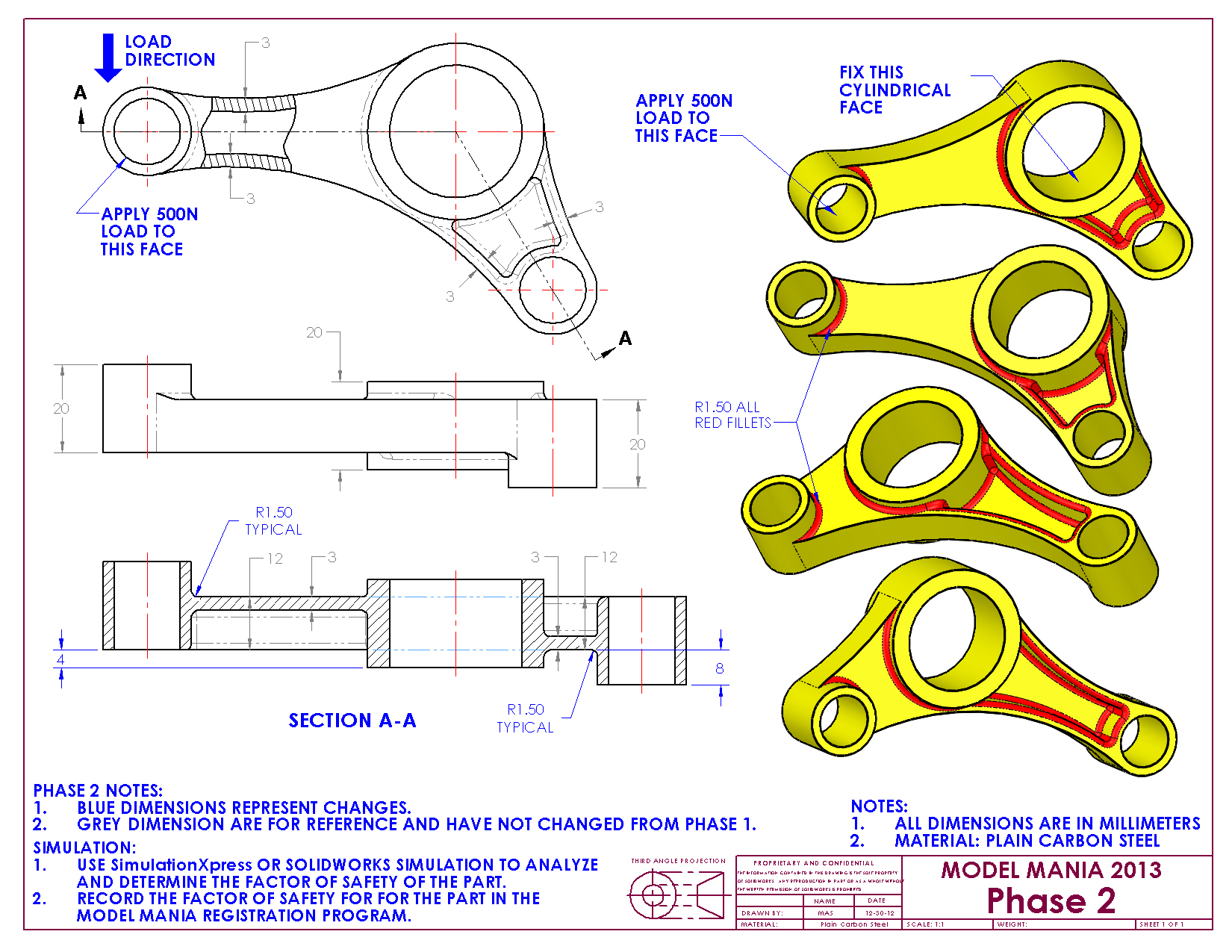
Would there be a possibility to shell still or is the approach as I suspect to remove the material by using extrude or perhaps using tbraxtons method.
Aug 24, 2023
04:19 PM
- Mark as New
- Bookmark
- Subscribe
- Mute
- Subscribe to RSS Feed
- Permalink
- Notify Moderator
Please log in to access translation
Aug 24, 2023
04:19 PM
I would stick to my previous answer, but each cylinder and each "floor" would need to be created individually.
There is always more to learn in Creo.
Aug 24, 2023
04:24 PM
- Mark as New
- Bookmark
- Subscribe
- Mute
- Subscribe to RSS Feed
- Permalink
- Notify Moderator
Please log in to access translation
Aug 24, 2023
04:24 PM
In general, if I am aware of a requirement to be able to "morph" the model into two or more variants, that will often influence how I would build the model. In these examples you refer to where the model needs to be changed, I would attempt to build this intent into a single model.
========================================
Involute Development, LLC
Consulting Engineers
Specialists in Creo Parametric
Involute Development, LLC
Consulting Engineers
Specialists in Creo Parametric
Aug 24, 2023
04:54 PM
- Mark as New
- Bookmark
- Subscribe
- Mute
- Subscribe to RSS Feed
- Permalink
- Notify Moderator
Please log in to access translation
Aug 24, 2023
04:54 PM
I was trying to do it blindly as in not see what needs to be changed while creating the first model, as were the rules during the original contest, however I think you raised quite a valid point; I should try to see if I can use that information to make my model more morphable, thank you very much for the inspiration.
Aug 24, 2023
04:12 PM
- Mark as New
- Bookmark
- Subscribe
- Mute
- Subscribe to RSS Feed
- Permalink
- Notify Moderator
Please log in to access translation
Aug 24, 2023
04:12 PM
I would create it this way:
- Extrude 3 cylinders
- Extrude three walls (Using Thin intrudes on inside of cylinders)
- Extrude floor using project
- Add rounds
There is always more to learn in Creo.
Aug 24, 2023
05:06 PM
- Mark as New
- Bookmark
- Subscribe
- Mute
- Subscribe to RSS Feed
- Permalink
- Notify Moderator
Please log in to access translation
Aug 24, 2023
05:06 PM
I didn't think of extruding the cylinders first, that would make changing the model easier for this for sure. Could you please elaborate what you mean by "Extrude three walls (Using Thin intrudes on inside of cylinders)". I do not quite understand what this means using three intrudes on inside of cylinder. Below is what I attempted.
Aug 25, 2023
08:17 AM
- Mark as New
- Bookmark
- Subscribe
- Mute
- Subscribe to RSS Feed
- Permalink
- Notify Moderator
Please log in to access translation
Aug 25, 2023
08:17 AM
Looking at your video, the thin extrude would work the way you are creating the cylinders as solid, then extruding holes later. I was extruding cylinder walls that are 2.5 mm thick. When thickening a line by 3 mm that is tangent to the cylinder it thickens 0.5 mm inside the cylinder.
In your video, the thin extrude does not work because the thickining lines clash at the bottom of the large cylinder. Try going around the outer perimeter with your lines and it should work fine.
There is always more to learn in Creo.
Aug 25, 2023
04:00 AM
- Mark as New
- Bookmark
- Subscribe
- Mute
- Subscribe to RSS Feed
- Permalink
- Notify Moderator
Please log in to access translation
Aug 25, 2023
04:00 AM
If you're on Creo 7 or later, this sounds like a job for multibody modeling. Make the cylinders and the connecting parts as separate bodies. Here's a quick demo:
- Make a master sketch containing the three circles and the tangent lines.
- Use Sketch Regions to extrude the entire sketch (including the cylinders) to the base thickness.
- Extrude only the three circles, using Sketch Regions, as a separate body.
- Shell the main body.
- Subtract the cylinder body from the main body, while keeping both (so don't remove the cylinder body).
- Shell the cylinder body.
- Merge the two bodies together.
If you don't like using sketch regions (to be honest, I don't), you could do the same thing by just constraining the cylinder extrude to the first extrude sketch. That's probably better, to be honest. Fewer references that risk breaking.
Aug 25, 2023
06:45 AM
- Mark as New
- Bookmark
- Subscribe
- Mute
- Subscribe to RSS Feed
- Permalink
- Notify Moderator
Please log in to access translation
Aug 25, 2023
06:45 AM
I just learned that you can extrude sketch regions and what multibody modelling is, this is so good. Thank you very much for the guidance, I never realised the significance of bodies before this.
Aug 25, 2023
11:38 AM
- Mark as New
- Bookmark
- Subscribe
- Mute
- Subscribe to RSS Feed
- Permalink
- Notify Moderator
Please log in to access translation
Aug 25, 2023
11:38 AM
There is always more than one way to capture design intent and I encourage you to review all methods and adopt what makes sense for you.
I use multibody extensively on parts that go into mass production. I would not use multibody on a part this simple as a preference. I do not default to sketch regions as a preferred approach either. This is driven by how I determine the best way to capture design intent for the design and the environment in which the data is used.
If the stated goal was to use a master sketch with a shell and minimize feature count, I would propose this as a method which captures the dimensioning scheme useful to produce the drawing. It pays to think ahead when building models and the best Creo users are always considering how to exploit the power of Creo to minimize rework downstream.
========================================
Involute Development, LLC
Consulting Engineers
Specialists in Creo Parametric
Involute Development, LLC
Consulting Engineers
Specialists in Creo Parametric
Aug 25, 2023
01:16 PM
- Mark as New
- Bookmark
- Subscribe
- Mute
- Subscribe to RSS Feed
- Permalink
- Notify Moderator
Please log in to access translation
Aug 25, 2023
01:16 PM
Ok yes that's definitely better than my method where I started off in surfaces; merged, solidified and then could only shell one body. My goal until yesterday was to get more familiar with surfaces, but now that I am a bit more familiar with both multibody modelling and surfacing, I think I will try multiple approaches.

Could you kindly elaborate on "how to exploit the power of Creo to minimize rework downstream." because I am not entirely sure what my goal should be while designing right now, should it be to minimize features used, ability to change dimensions or reduce the time spent. Of course I realise that's quite a broad question and depends on what my goals are but as a student I am lacking a bit of direction and would really appreciate your advice.
Another question how are you creating the holes in the model because for concentric circles I have been using the outside circles to create axes and then using that axis to create which I feel is quite a tedious method.

I would like to end by thanking you, I really appreciate your guidance.
Best regards,
Ibrahim Tayyab
Aug 25, 2023
01:56 PM
- Mark as New
- Bookmark
- Subscribe
- Mute
- Subscribe to RSS Feed
- Permalink
- Notify Moderator
Please log in to access translation
Aug 25, 2023
01:56 PM
For my two cents, I believe modeling to design intent (How do features relate to each other?) (and how it going to be annotated) is more important than feature reduction. Also, too much stuff in one feature can make future changes more difficult.
Axis are created when a full circle is created. If you have layer rules, they may be automatically added to a layer that is hidden. If I want an axis in the center of an arc, I will add a Point from the datum section of the ribbon, not to be confused with the Construction Point in the sketching section. This will create an axis when the sketch is extruded.

There is always more to learn in Creo.
Aug 25, 2023
02:45 PM
- Mark as New
- Bookmark
- Subscribe
- Mute
- Subscribe to RSS Feed
- Permalink
- Notify Moderator
Please log in to access translation
Aug 25, 2023
02:45 PM
The answer on how to best leverage Creo changes constantly. This is not "taught" in any academic setting that I have experience with. It has more to do with understanding how to leverage the CAD tool (Creo, NX, Catia etc.) to maximize the ROI on the people hardware and software purchased. Most users develop this on the job.
Think about primarily capturing design intent in your models and features in the models. This should almost always be the primary consideration. Try to anticipate how a model may need to change during development and build flexibility and robustness (ability to regenerate) by managing parent child relationships. Keep things as simple as possible while capturing intent (minimize parent child dependencies and not necessarily feature count.)
Depending on what the deliverable is (your design CAD data) the approach to modeling can change.
A few (not all) considerations would be the following:
Creating a fabrication or an inspection drawing (this relates to the dimensioning scheme used in the features that can be shown on the drawing) If you are not able to show dimensions from the model then you will need to create the needed dimensions as an example of rework.
Manufacturing process used to make the parts (will tooling be designed using your part models?) Maybe you need the model to support more than one manufacturing process requiring some changes to dimensions or geometry.
Will the models be used for any CAE simulation or analysis? This means you need to consider how to support that with model geometry (i.e., remove rounds for stress analysis meshing)
My holes used the axis that exists from extrude 2.

========================================
Involute Development, LLC
Consulting Engineers
Specialists in Creo Parametric
Involute Development, LLC
Consulting Engineers
Specialists in Creo Parametric


