
Turn on suggestions
Auto-suggest helps you quickly narrow down your search results by suggesting possible matches as you type.
Showing results for
Please log in to access translation
Turn on suggestions
Auto-suggest helps you quickly narrow down your search results by suggesting possible matches as you type.
Showing results for
- Community
- Creo+ and Creo Parametric
- 3D Part & Assembly Design
- Re: Radial pattern dimension out of place
Translate the entire conversation x
Please log in to access translation
Options
- Subscribe to RSS Feed
- Mark Topic as New
- Mark Topic as Read
- Float this Topic for Current User
- Bookmark
- Subscribe
- Mute
- Printer Friendly Page
Radial pattern dimension out of place
Oct 28, 2015
02:42 AM
- Mark as New
- Bookmark
- Subscribe
- Mute
- Subscribe to RSS Feed
- Permalink
- Notify Moderator
Please log in to access translation
Oct 28, 2015
02:42 AM
Radial pattern dimension out of place
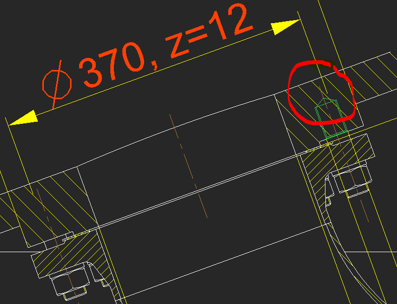
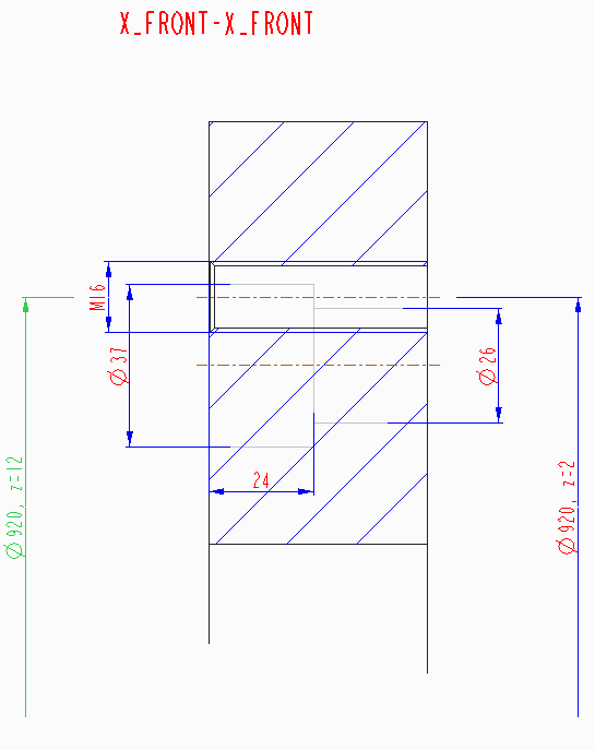
Using Creo 2 M110. When the dimension of the hole of radial axis pattern is shown on the view, where the cross section doesn't go through the hole, i.e. the hole is placed outside of cross section, the dimension doesn't fit to the actual hole axis (see figure below). I haven't had problems with that before but I might change some drawing options, however I don't know if those are the reason and which one would affect this behaviour. I would need advice, what is the reason and how to fix that.
This thread is inactive and closed by the PTC Community Management Team. If you would like to provide a reply and re-open this thread, please notify the moderator and reference the thread. You may also use "Start a topic" button to ask a new question. Please be sure to include what version of the PTC product you are using so another community member knowledgeable about your version may be able to assist.
Labels:
- Labels:
-
2D Drawing
5 REPLIES 5
Oct 28, 2015
08:02 AM
- Mark as New
- Bookmark
- Subscribe
- Mute
- Subscribe to RSS Feed
- Permalink
- Notify Moderator
Please log in to access translation
Oct 28, 2015
08:02 AM
If the cross section doesn't go thru the center of the hole, you can not "fix" this with a drawing option.
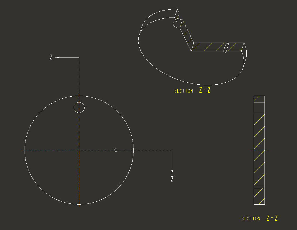
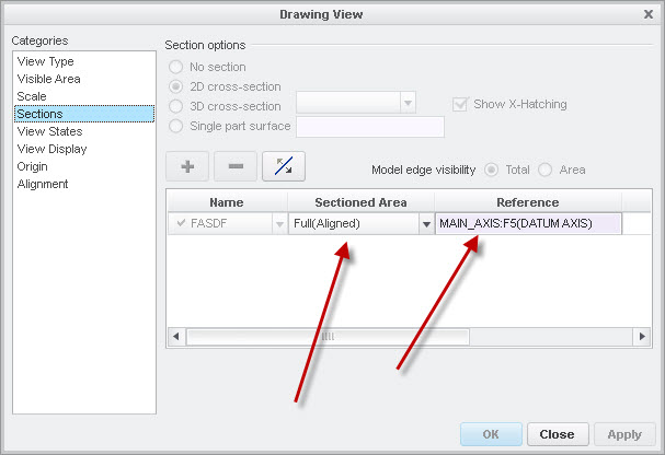
You can however, make an offset cross section that goes thru the hole and then use full (aligned) and select the center axis of the part.
Nov 02, 2015
08:25 AM
- Mark as New
- Bookmark
- Subscribe
- Mute
- Subscribe to RSS Feed
- Permalink
- Notify Moderator
Please log in to access translation
Nov 02, 2015
08:25 AM
In the old days (WF3), when the hole was not on section plane you could show axis and then place the dimension for that specific hole with axis shown. Dimension was placed right on the axis. If you would try to create draft dimension for that axis it would not show correct length/diameter, whereas shown (model) dimension was showing correct diameter.
As it may be seen from the picture in my original post, axis is shown correctly (in the center of the green - selected - hole), whereas dimension of that hole is shown on its original place (where it would actually be if the view section would be oriented parallel to the screen) and it doesn't matter for which hole on pitch circle I try to place the dimension for - it is always shown on presumed to be place.
As this is change in showing dimensions (comparing to the old days), I assumed this would something had to do with detail settings.
Nov 02, 2015
03:15 PM
- Mark as New
- Bookmark
- Subscribe
- Mute
- Subscribe to RSS Feed
- Permalink
- Notify Moderator
Please log in to access translation
Nov 02, 2015
03:15 PM
Jurij,
can you upload example data (model+drawing) for testing purposes ?
See How to attach file when you Reply to a discussion.
MH
Martin Hanák
Nov 10, 2015
01:19 AM
- Mark as New
- Bookmark
- Subscribe
- Mute
- Subscribe to RSS Feed
- Permalink
- Notify Moderator
Please log in to access translation
Nov 10, 2015
01:19 AM
Martin,
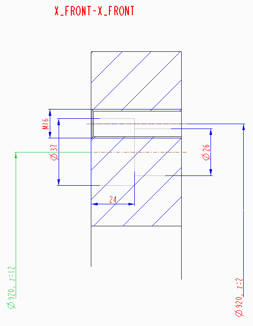
Attached are the drawing and model - see dimension Ø920, z=12, which is out of place and should be attached to the lower axis line.
Regards,
Jurij
Nov 10, 2015
02:42 AM
- Mark as New
- Bookmark
- Subscribe
- Mute
- Subscribe to RSS Feed
- Permalink
- Notify Moderator
Please log in to access translation
Nov 10, 2015
02:42 AM
Jurij,
test no.1 ... drawing opened in in CR2 M070 ... correct display
test no.2 ... drawing opened in in CR2 M110, CR2 M190, CR3 M060 ... incorrect display
Please report the problem to PTC Support. I looks like software bug.
MH
Martin Hanák


