
Turn on suggestions
Auto-suggest helps you quickly narrow down your search results by suggesting possible matches as you type.
Showing results for
Please log in to access translation
Turn on suggestions
Auto-suggest helps you quickly narrow down your search results by suggesting possible matches as you type.
Showing results for
Community Tip - New to the community? Learn how to post a question and get help from PTC and industry experts! X
- Community
- Creo+ and Creo Parametric
- 3D Part & Assembly Design
- Re: Reference/display dimensions from part in an a...
Translate the entire conversation x
Please log in to access translation
Options
- Subscribe to RSS Feed
- Mark Topic as New
- Mark Topic as Read
- Float this Topic for Current User
- Bookmark
- Subscribe
- Mute
- Printer Friendly Page
Reference/display dimensions from part in an assembly drawing
Feb 13, 2013
02:00 PM
- Mark as New
- Bookmark
- Subscribe
- Mute
- Subscribe to RSS Feed
- Permalink
- Notify Moderator
Please log in to access translation
Feb 13, 2013
02:00 PM
Reference/display dimensions from part in an assembly drawing
How do you display a dimension on an assembly drawing that references a dimension from a feature in a part of that assembly?
I've tried
&d###:file_name
&d###:file_name.prt
&d###:feature_number:file_name
I am trying to dimension a counter bore hole callout for a part in an inseparable assembly.
Thanks
This thread is inactive and closed by the PTC Community Management Team. If you would like to provide a reply and re-open this thread, please notify the moderator and reference the thread. You may also use "Start a topic" button to ask a new question. Please be sure to include what version of the PTC product you are using so another community member knowledgeable about your version may be able to assist.
Solved! Go to Solution.
Labels:
- Labels:
-
2D Drawing
ACCEPTED SOLUTION
Accepted Solutions
Feb 14, 2013
01:02 PM
- Mark as New
- Bookmark
- Subscribe
- Mute
- Subscribe to RSS Feed
- Permalink
- Notify Moderator
Please log in to access translation
Feb 14, 2013
01:02 PM
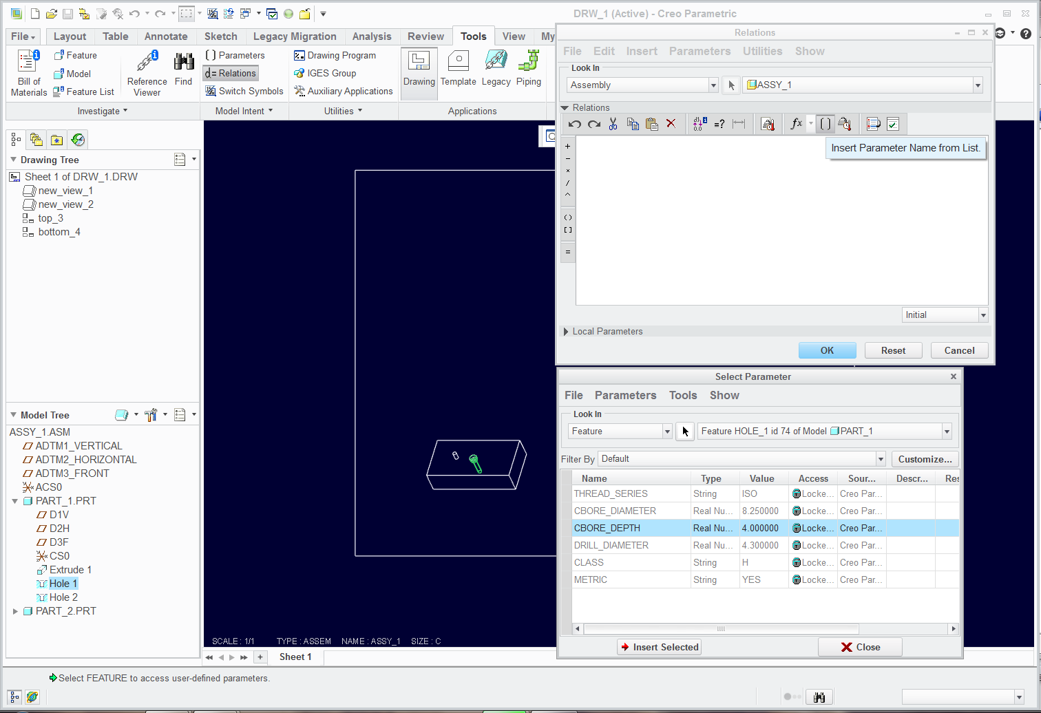
I am not sure if WF4 has the same or similar interface to Creo that is why I didn't add it... but there is a button in Creo that lets you get to all the parameters of any feature, part, assembly, etc.
See if any of this looks familiar. You should have an Insert Parameter button somewhere... you should have the features shown in the model tree (for ease of use)... and you select the feature in the Parameter list and Insert Selected. Then you build the relation you want.
13 REPLIES 13
Feb 13, 2013
03:18 PM
- Mark as New
- Bookmark
- Subscribe
- Mute
- Subscribe to RSS Feed
- Permalink
- Notify Moderator
Please log in to access translation
Feb 13, 2013
03:18 PM
Show Annotation and pick the part or feature in the model tree. Once you show it, you can get the code by with Switch Symbols.
Feb 13, 2013
03:23 PM
- Mark as New
- Bookmark
- Subscribe
- Mute
- Subscribe to RSS Feed
- Permalink
- Notify Moderator
Please log in to access translation
Feb 13, 2013
03:23 PM
I guess the syntax is &dnnn:N where "N" is the assigned number to each part in the assembly, not specifically tied to the part itself. This makes sense when you have multiples of the same part, I guess.
Feb 13, 2013
05:52 PM
- Mark as New
- Bookmark
- Subscribe
- Mute
- Subscribe to RSS Feed
- Permalink
- Notify Moderator
Please log in to access translation
Feb 13, 2013
05:52 PM
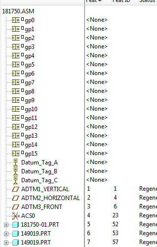
Tony, the above syntax you offered isn't working. See picture for clarity.
I'm trying to reference d259 in part 181750-01 in the tree.
I've tried
&d259:5
&d259:52
&d259:1
It just takes the & sign away from the note on some of the attempts.
We've been trying to figure this out for a while... Any help would be appreciated.
Feb 13, 2013
06:39 PM
- Mark as New
- Bookmark
- Subscribe
- Mute
- Subscribe to RSS Feed
- Permalink
- Notify Moderator
Please log in to access translation
Feb 13, 2013
06:39 PM
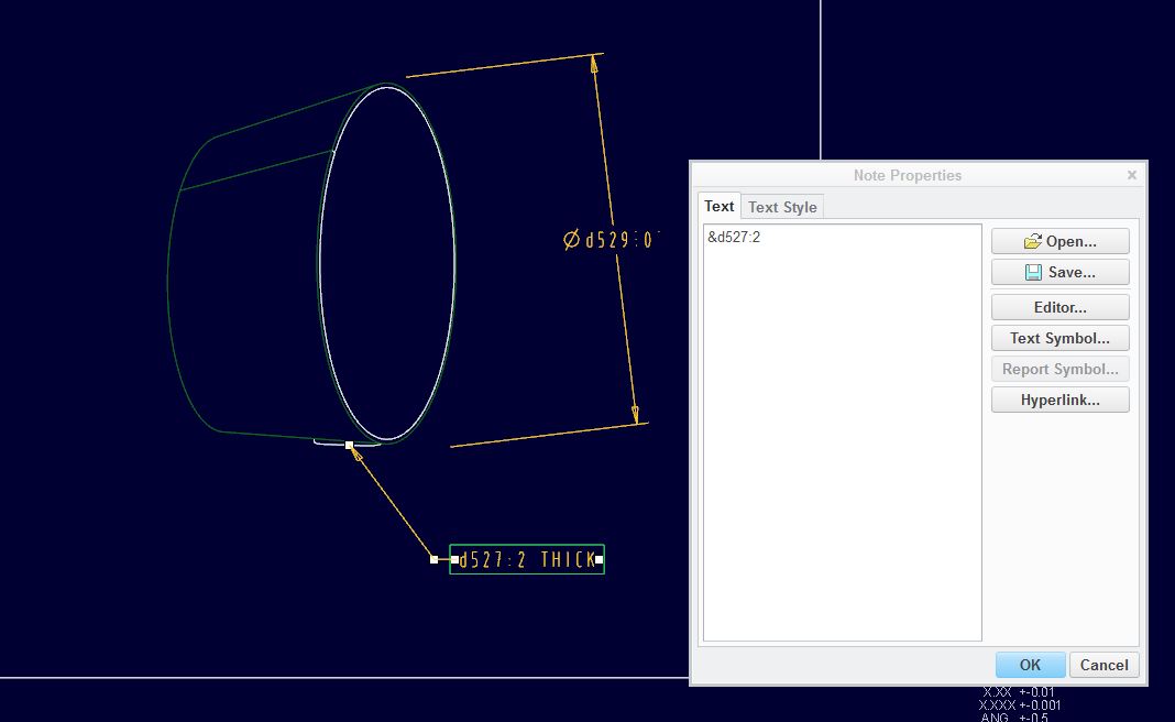
When I created the note from the one dimension, I first selected it with Show Annotations by selecting the feature in the part through the model tree. After that, I used the annotation in the note just as I saw it on the screen.
Can you post the files in a zip, or something similar to test for you? Also, what version are you using?
Feb 14, 2013
11:23 AM
- Mark as New
- Bookmark
- Subscribe
- Mute
- Subscribe to RSS Feed
- Permalink
- Notify Moderator
Please log in to access translation
Feb 14, 2013
11:23 AM
I am using Pro E Wildfire 4
I attached a sample of what I'm trying to do. Basically I want to be able to link the counterbore diameter and depth in the hole diameter dimension for one part in an assembly of multiple parts.
It sounds like it should be very simple...
Thanks for all your help,
Tim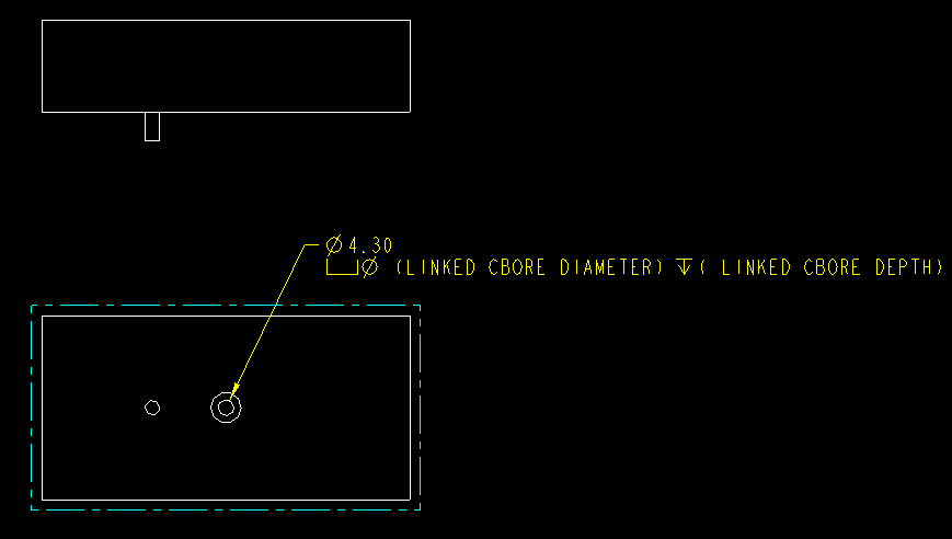
Feb 14, 2013
12:05 PM
- Mark as New
- Bookmark
- Subscribe
- Mute
- Subscribe to RSS Feed
- Permalink
- Notify Moderator
Please log in to access translation
Feb 14, 2013
12:05 PM
This is indeed interesting behavior. I will have to look into this further (that's code to ask tech support).
You can get what you want fairly easily but it seems to be either a bug or a limitation. I need to test it with some current parts and different config.pro settings to see if I simply inherited it in my session or if this is common behavior.
This is what I saw:
- If you overwrite a drafting dimension (driven) with @O and add any &d{whatever:N}, it removes all the &.
- If you create a drafting note and add the &d{whatever:N}, it behaves as expected; it displayed the dimension value and pre/suffixes.
- If you "show" the original sub-part hole diameter, you can add all the &d{whatever:N} you want and they show as expected.
Since I am on Creo 2.0, you probably can't open my files. Let me know if this echoes the behavior you see in WF4
Feb 14, 2013
12:10 PM
- Mark as New
- Bookmark
- Subscribe
- Mute
- Subscribe to RSS Feed
- Permalink
- Notify Moderator
Please log in to access translation
Feb 14, 2013
12:10 PM
- Oh, and you cannot add &d{whatever:N} to a driven dimension.
Feb 14, 2013
12:29 PM
- Mark as New
- Bookmark
- Subscribe
- Mute
- Subscribe to RSS Feed
- Permalink
- Notify Moderator
Please log in to access translation
Feb 14, 2013
12:29 PM
In order to use exactly what you have, you need ot build assembly relations:
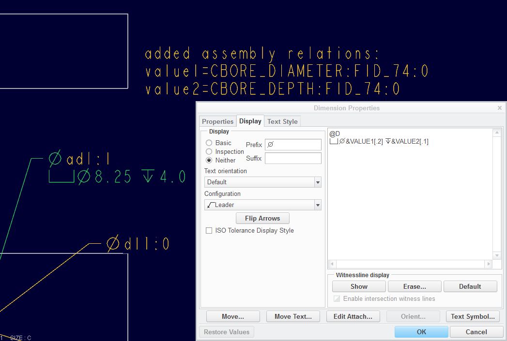
The relations were created directly from the drawing.
Do you know how to find feature parameters and add them in relations?
Feb 14, 2013
12:32 PM
- Mark as New
- Bookmark
- Subscribe
- Mute
- Subscribe to RSS Feed
- Permalink
- Notify Moderator
Please log in to access translation
Feb 14, 2013
12:32 PM
Everything you wrote echos what I'm seeing.
Showing a dimsion, your 3rd bullet, does work correctly and that will work for us. The only problem with that is you cannot place GD&T on that dimension using datums from the Assembly. Which is probably better practice to place th datums in the part, rather than the assembly anyway.
It would be nice to know how to add these dimensions in a drafting dimension still.
Thanks,
Feb 14, 2013
12:54 PM
- Mark as New
- Bookmark
- Subscribe
- Mute
- Subscribe to RSS Feed
- Permalink
- Notify Moderator
Please log in to access translation
Feb 14, 2013
12:54 PM
The relations worked also. Do you have a reference website or document explaining the syntax of the relations? I'm unclear why
VALUE1=CBORE_DIAMETER:FID_74:0
VALUE2=CBORE_DEPTH:FID_74:0
was typed the way it was.
Thanks
Feb 14, 2013
01:02 PM
- Mark as New
- Bookmark
- Subscribe
- Mute
- Subscribe to RSS Feed
- Permalink
- Notify Moderator
Please log in to access translation
Feb 14, 2013
01:02 PM
I am not sure if WF4 has the same or similar interface to Creo that is why I didn't add it... but there is a button in Creo that lets you get to all the parameters of any feature, part, assembly, etc.
See if any of this looks familiar. You should have an Insert Parameter button somewhere... you should have the features shown in the model tree (for ease of use)... and you select the feature in the Parameter list and Insert Selected. Then you build the relation you want.
Feb 14, 2013
01:10 PM
- Mark as New
- Bookmark
- Subscribe
- Mute
- Subscribe to RSS Feed
- Permalink
- Notify Moderator
Please log in to access translation
Feb 14, 2013
01:10 PM
Yes, this all works...
Thank you very much
Feb 14, 2013
01:33 PM
- Mark as New
- Bookmark
- Subscribe
- Mute
- Subscribe to RSS Feed
- Permalink
- Notify Moderator
Please log in to access translation
Feb 14, 2013
01:33 PM
My pleasure! ...and have a great day 


