
Turn on suggestions
Auto-suggest helps you quickly narrow down your search results by suggesting possible matches as you type.
Showing results for
Please log in to access translation
Turn on suggestions
Auto-suggest helps you quickly narrow down your search results by suggesting possible matches as you type.
Showing results for
Community Tip - You can change your system assigned username to something more personal in your community settings. X
- Community
- Creo+ and Creo Parametric
- 3D Part & Assembly Design
- Re: Sheet Metal Roller Bead
Translate the entire conversation x
Please log in to access translation
Options
- Subscribe to RSS Feed
- Mark Topic as New
- Mark Topic as Read
- Float this Topic for Current User
- Bookmark
- Subscribe
- Mute
- Printer Friendly Page
Sheet Metal Roller Bead
Feb 14, 2015
09:08 AM
- Mark as New
- Bookmark
- Subscribe
- Mute
- Subscribe to RSS Feed
- Permalink
- Notify Moderator
Please log in to access translation
Feb 14, 2015
09:08 AM
Sheet Metal Roller Bead
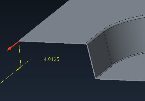
I want to add a bead to a sheet metal part. It will follow the contour of another feature already placed. I could do a form tool and punch it in the part but I was hoping there is another way. I would like to sketch my trajectory on the part and have a the shape sweep that. But so far I dont see a way.
Here is a sample picture of something like I want.

This would be the tool that would do it,
http://www.mate.com/en/products-and-parts/fabrication-solutions/rollerball/http://
This thread is inactive and closed by the PTC Community Management Team. If you would like to provide a reply and re-open this thread, please notify the moderator and reference the thread. You may also use "Start a topic" button to ask a new question. Please be sure to include what version of the PTC product you are using so another community member knowledgeable about your version may be able to assist.
Labels:
- Labels:
-
General
20 REPLIES 20
Feb 14, 2015
08:45 PM
- Mark as New
- Bookmark
- Subscribe
- Mute
- Subscribe to RSS Feed
- Permalink
- Notify Moderator
Please log in to access translation
Feb 14, 2015
08:45 PM
I am not a fan of the punch tools since they are kept outside the model. I opt for a surface form tool.
That way I generate the surface just like you suggest and then using the surface to form the metal isn't too troublesome at that point.
You can therefore use all your familiar commands to create the surface including reusing common references.
Feb 14, 2015
11:57 PM
- Mark as New
- Bookmark
- Subscribe
- Mute
- Subscribe to RSS Feed
- Permalink
- Notify Moderator
Please log in to access translation
Feb 14, 2015
11:57 PM
http://www.mate.com/en/products-and-parts/fabrication-solutions/rollerball(The original link is mis-posted)
Interesting tool - I like the video
The Mate Rollerball™ tool creates stiffening ribs and decorative beads in sheet metal parts without a secondary operation. It is available in popular tool styles including: Ultraform for Thick Turret, Thin Turret, 112/114, and Trumpf style.
Feb 17, 2015
09:27 AM
- Mark as New
- Bookmark
- Subscribe
- Mute
- Subscribe to RSS Feed
- Permalink
- Notify Moderator
Please log in to access translation
Feb 17, 2015
09:27 AM
Sorry about the link. I didnt notice the extra http remaining after I cut and pasted.
Looking at other cad packages It looks like they have a feature specifically for beads. I dont see this in Creo. I dont like form features either but since it would take more work to make the feature come out correct without a form tool , and I will be needing a very similar feature in a few other other parts Im afraid the form tool is what I will have to use. PTC reallly needs to add funcitonality for a bead feature. Thanks.
Feb 17, 2015
10:25 AM
- Mark as New
- Bookmark
- Subscribe
- Mute
- Subscribe to RSS Feed
- Permalink
- Notify Moderator
Please log in to access translation
Feb 17, 2015
10:25 AM
I just made a quick look for beading in other packages; only found it so far in NX NX Sheetmetal 18 BEAD - YouTube and SolidEdge Solid Edge Short: Sheet Metal in Solid Edge ST6 - YouTube courtesy of a compliant that Inventor did not. Overdue Improvements to Inventor Sheet Metal: - Autodesk Community which is a really interesting list of things for sheet metal to do. I did notice that the Solidedge version is unrealistic in its handling of sheet metal - the beads would certainly collapse if they were bent like the model shows.
Feb 17, 2015
11:17 AM
- Mark as New
- Bookmark
- Subscribe
- Mute
- Subscribe to RSS Feed
- Permalink
- Notify Moderator
Please log in to access translation
Feb 17, 2015
11:17 AM
i think the sketched form tool is your answer. they have added that from creo 2.0.
you have to just sketch the shape..it has to be closed sketch.
Feb 17, 2015
12:55 PM
- Mark as New
- Bookmark
- Subscribe
- Mute
- Subscribe to RSS Feed
- Permalink
- Notify Moderator
Please log in to access translation
Feb 17, 2015
12:55 PM
I never figured out how to correctly use the sketched forms.
Ken, the feature is there, it just isn't prettied up like other offerings.
A path, swept arc, and quilt form. Done:
Feb 17, 2015
02:09 PM
- Mark as New
- Bookmark
- Subscribe
- Mute
- Subscribe to RSS Feed
- Permalink
- Notify Moderator
Please log in to access translation
Feb 17, 2015
02:09 PM
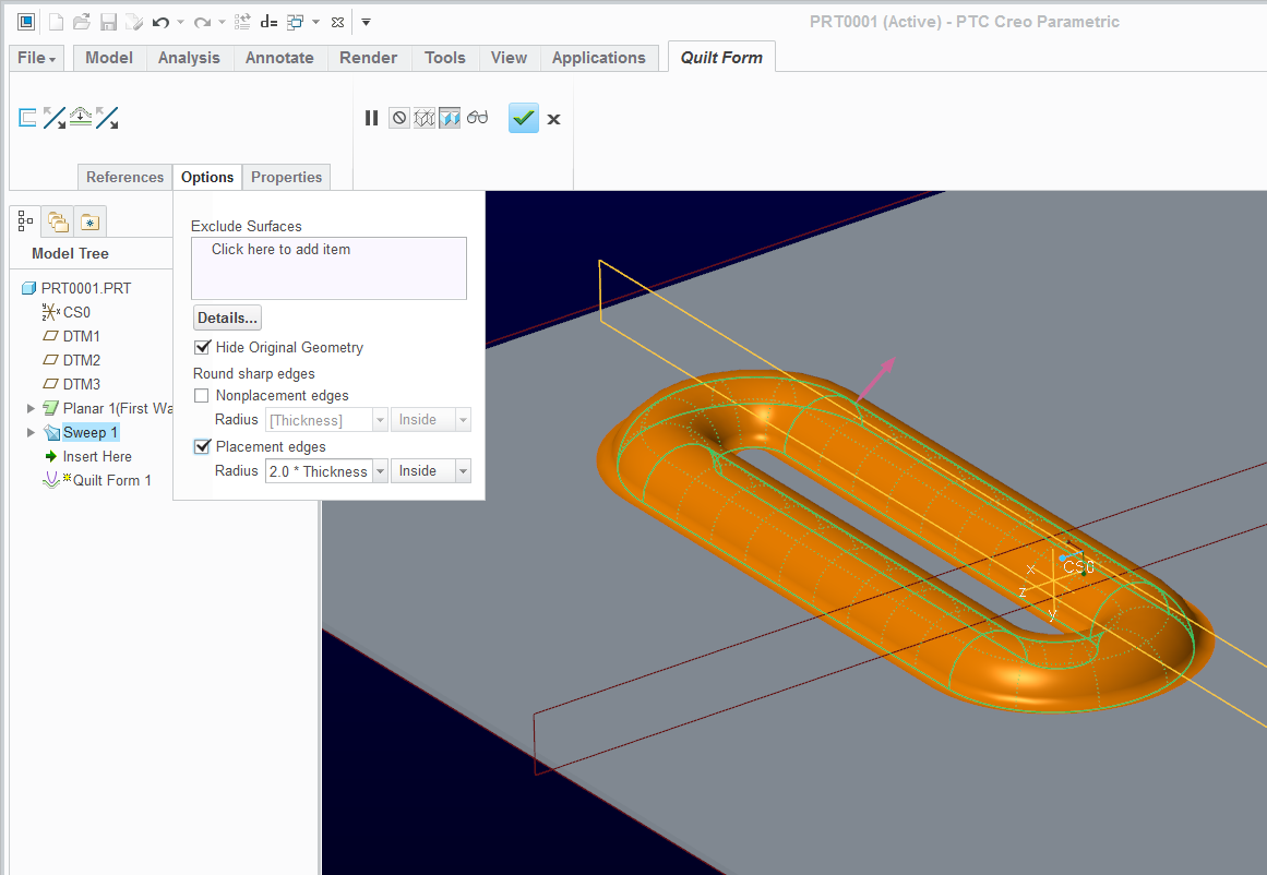
Ok this looks promising. I have not tried this method before and so far I must be missing something as I cannot get it to work.
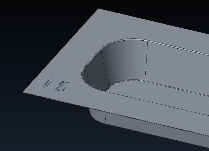
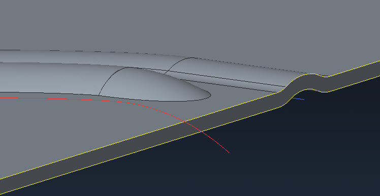
Here is my panel with the swept surface along the sketched trajectory (the cutout on the left). The straight bead along the bottom I did with a form tool.
When I get in to Quilt Form and select the surface previously created I cannot get it the create the sheet metal feature I tried various combations of the options. Thanks for the help with this.
Feb 17, 2015
02:20 PM
- Mark as New
- Bookmark
- Subscribe
- Mute
- Subscribe to RSS Feed
- Permalink
- Notify Moderator
Please log in to access translation
Feb 17, 2015
02:20 PM
Make sure the quilt goes through the material thickness.
Be sure to radius your corners so the quilt doesn't double back on itself. (just guessing here)
Feb 17, 2015
02:28 PM
- Mark as New
- Bookmark
- Subscribe
- Mute
- Subscribe to RSS Feed
- Permalink
- Notify Moderator
Please log in to access translation
Feb 17, 2015
02:28 PM
...and try switching the direction arrows on the form feature creation 
Creo 2.0 full version attached.
Feb 17, 2015
02:46 PM
- Mark as New
- Bookmark
- Subscribe
- Mute
- Subscribe to RSS Feed
- Permalink
- Notify Moderator
Please log in to access translation
Feb 17, 2015
02:46 PM
It looks like its the open ends of the sweep causing the problem. If I make a comple loop of my sweep it works. Im back to the form too for this it looks like.
Feb 17, 2015
02:52 PM
- Mark as New
- Bookmark
- Subscribe
- Mute
- Subscribe to RSS Feed
- Permalink
- Notify Moderator
Please log in to access translation
Feb 17, 2015
02:52 PM
I too would like to know this and I only know how to do it by using a form.
I love sketched forms, but that just makes a sink unless I'm doing it wrong.... right?!?!? As a one click type solution a sketched form is pretty sweet, saves a ton of time combining all the offset and merge action, but is there a way to make a thin, or sweep it as a ball somehow? Please share your method here, my technique probably goes back to pro 17.
I have oil canned all kinds of sheet parts for stiffness but a separate form tool is what I usually use. Since the rounds and interfaces can get wacky as well, I usually put those shapes on the form and get them to regenerate successfully on the punch then let it propogate away. I guess I have had better luck going crazy on the form to get the shape correct because once it's stable, it seems to stay put and behave.
I do not run PDM here, but when I have done this same dance at client sites, seems that the dependency gets found and the form part just checks in along with the rest of the parts like its normal. Maybe that's an admin setting somewhere I don't know, but personally I've never had an issue where the form gets lost or unattached or whatnot.
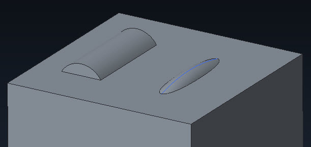
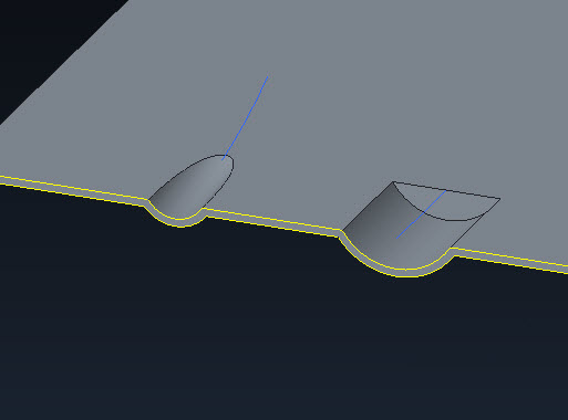
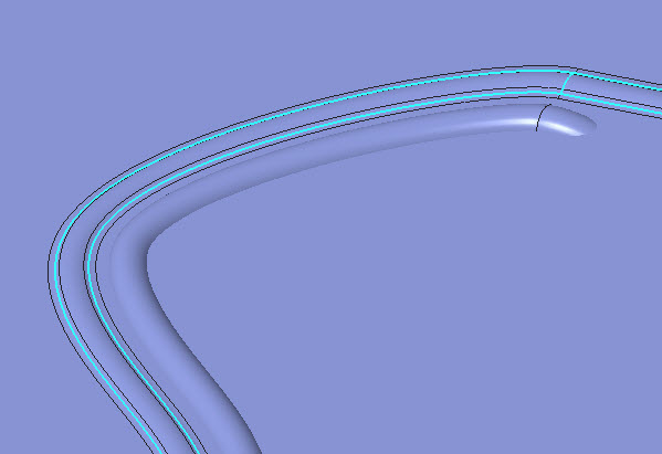
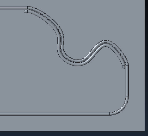
In any case here are three forms, the sketched one basically makes a sink and not a ringed ball deformation which seems to be the OP. I added the optional rounds to that and even some taper just to push it around. The other two shapes on the corner are both on a single form, one is a straight circle sweep, the other is arc based so the rounds work out, but you can see both trajectories because they merged over. Pictures below since they are so much easier to track.
tl;dr - would like to know how to do a ring shaped ball deformation please
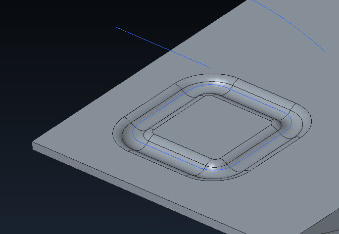
sketched form section
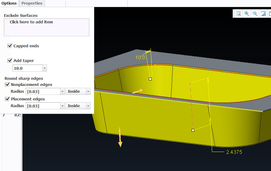
sketched form options as shown, sketch is closed loop rectangle with round fillets (8 entities)
form tool (old school?)
section view of forms
three forms, two pushes, one form, one closed loop, none exactly do the roller ball thing per the video above
roller ball like deformation from a form, but it's not quite Jedi level stuff....
Feb 17, 2015
03:24 PM
- Mark as New
- Bookmark
- Subscribe
- Mute
- Subscribe to RSS Feed
- Permalink
- Notify Moderator
Please log in to access translation
Feb 17, 2015
03:24 PM
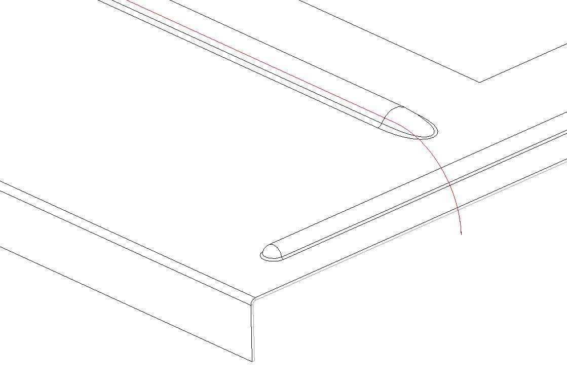
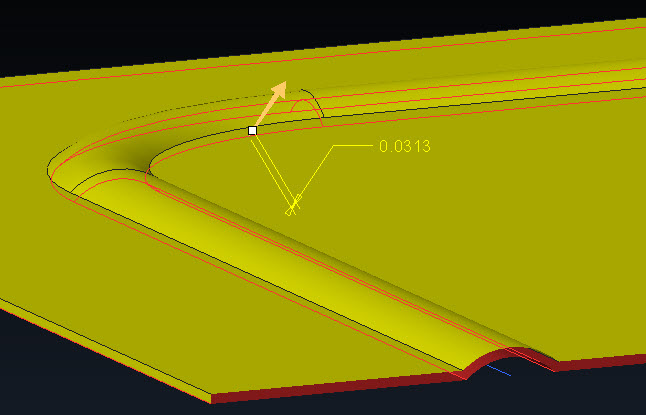
Gary, you gave me an idea and it worked. I did two additional sketches with a turn down on both ends of my original sketch. This causes the sweep to go off the surface and not have an uncapped end when the quilted form is created. Not sure if this is any less trouble than doing an outside form but maybe. At least the feature is contained in my part without an external reference. Thanks!
Feb 17, 2015
03:36 PM
- Mark as New
- Bookmark
- Subscribe
- Mute
- Subscribe to RSS Feed
- Permalink
- Notify Moderator
Please log in to access translation
Feb 17, 2015
03:36 PM
Are you surfacing this with trim's and merge and stuff??
Feb 17, 2015
03:54 PM
- Mark as New
- Bookmark
- Subscribe
- Mute
- Subscribe to RSS Feed
- Permalink
- Notify Moderator
Please log in to access translation
Feb 17, 2015
03:54 PM
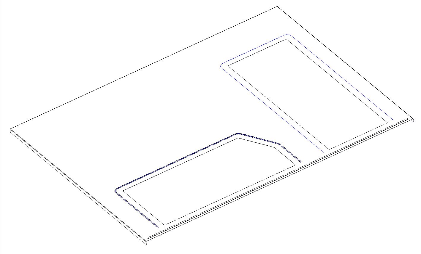
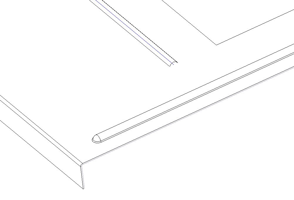
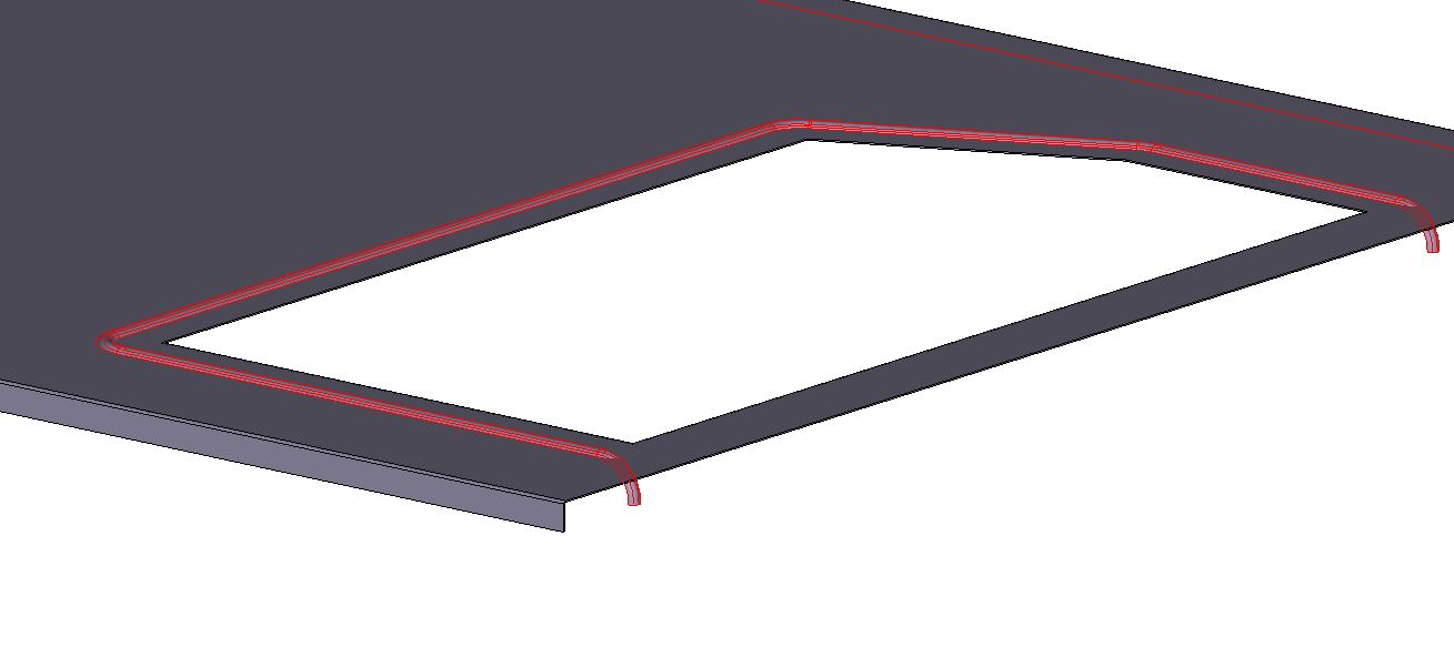
To recap. I have an irregular shaped cuttout that I wanted a bead around all but one side of it. I did an offset sketch to use as a trajectory. To get the ends of the form to work I did two additional sketches at each end that were normal the original sketch causing the trajectory to go into the z direction. I did a sweep using a surface. Then used the Quilt Form selecting the surface I just created. I did not have to do any surface trimming or merging. Im not great at describing stuff but hope that gets it.
Shown below is the surface feature as it follows the cutout and then shoots back in the z depth.
Feb 17, 2015
05:02 PM
- Mark as New
- Bookmark
- Subscribe
- Mute
- Subscribe to RSS Feed
- Permalink
- Notify Moderator
Please log in to access translation
Feb 17, 2015
05:02 PM
Gotcha, well as I said before I'm on the hunt for a trick on this if there is one. I know there are a bucket of ways to do it, especially on this site where there are Jedi everywhere here so forgive me if I undershoot or overshoot the topic here...
Anyways if the thought interests you and you need the model to be exact, you could surface your way to a quilt that is trimmed and merged until it will thicken. At that point you almost have a model that is too accurate but... anyways.. user friendly is not quite applicable to this style and for sure it's not sheet metal. Personally I'm a fan of the easy way it does most things now so some surfacing magic is a ton easier today.
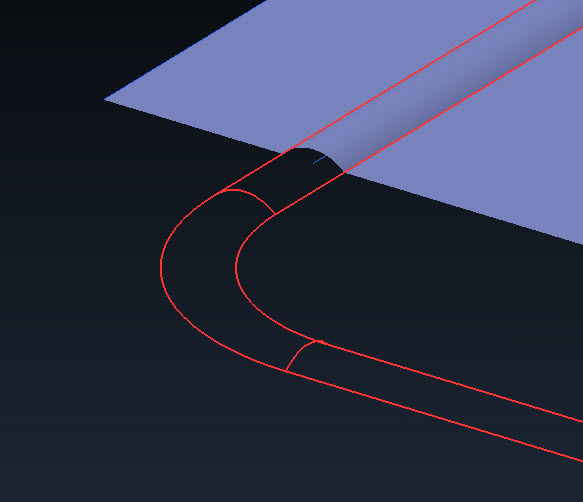
In any case, this might be 10x the work in most cases but I had a few ideas I wanted to try out as well so while they seem to have panned out, I'm not sure if I answered my own question so to speak. Shown here is a surface, then a wacky bead, then an offset of that bead, then another bead that dives down in Z like you did. It did thicken in the end so I have to assume all the tangent's and such are legit, but this isn't really the simple approach I'm looking for.
existing feature left, used as source to offset (could have been a cut or any edge/curve)
existing feature made very non-square just to make sure this method holds water, end of offset at right/below
cross section of thickened quilt, trajectory for original and offset (with dive in Z) visible
shapes of forms likely more complicated than necessary for 99% of life, but if it works here... should work anywhere
Feb 17, 2015
07:05 PM
- Mark as New
- Bookmark
- Subscribe
- Mute
- Subscribe to RSS Feed
- Permalink
- Notify Moderator
Please log in to access translation
Feb 17, 2015
07:05 PM
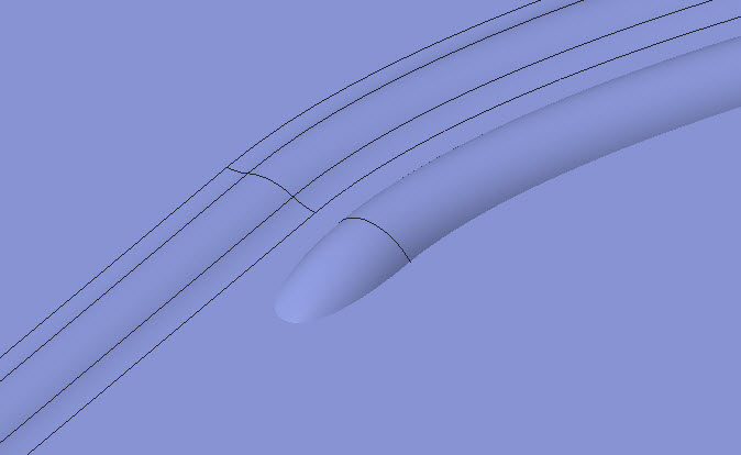
These work. I think the original idea for a capped end to the original sweep would be to revolve the ends and merge them to a single quilt. Then you have a true spherical end. Yes, more work... and yes, that should be the default for a dead end sketch form too. Looks like an idea should be submitted.
Feb 17, 2015
09:24 PM
- Mark as New
- Bookmark
- Subscribe
- Mute
- Subscribe to RSS Feed
- Permalink
- Notify Moderator
Please log in to access translation
Feb 17, 2015
09:24 PM
That curve at the end can be tightened to form a more spherical radius; it's a fairly clever solution that mimics the tool path - not identical, but close enough. I wonder on the CNC end what the 2D flat pattern software will make of the 3D curve trailing off like that.
Nov 28, 2016
05:23 PM
- Mark as New
- Bookmark
- Subscribe
- Mute
- Subscribe to RSS Feed
- Permalink
- Notify Moderator
Please log in to access translation
Nov 28, 2016
05:23 PM
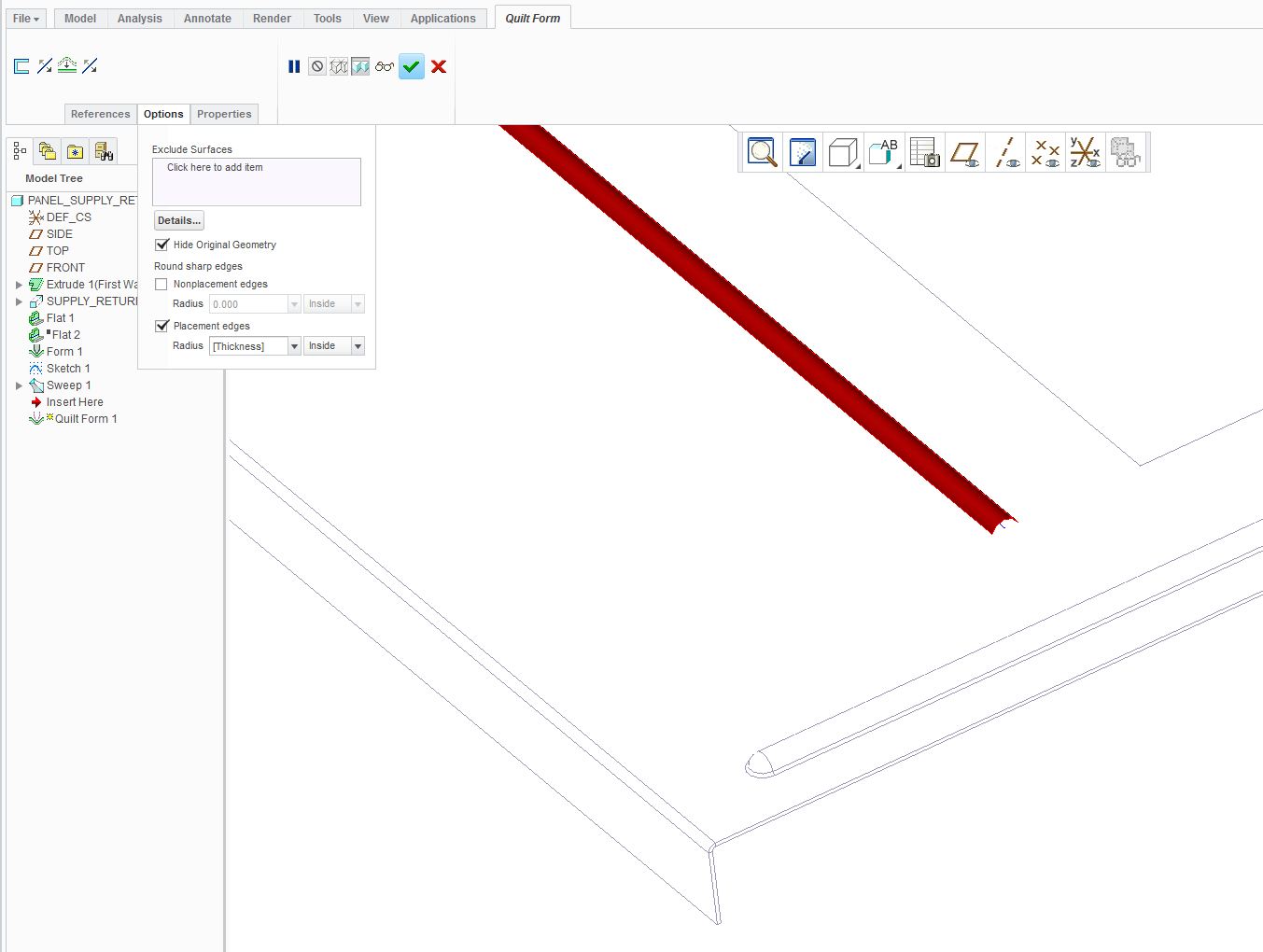
Funny, the "Quilt form" seems to not like rounds that become tangent to the plane on the "punch" side. And adding the rounds IN the feature doesn't work either. Not good. Am I missing something? You'd think the "placement" and "non placement" edges would work......
Nov 28, 2016
05:28 PM
- Mark as New
- Bookmark
- Subscribe
- Mute
- Subscribe to RSS Feed
- Permalink
- Notify Moderator
Please log in to access translation
Nov 28, 2016
05:28 PM
It likes to optionally add its own rounds based on the sheetmetal bend radius setting.
Nov 28, 2016
07:55 PM
- Mark as New
- Bookmark
- Subscribe
- Mute
- Subscribe to RSS Feed
- Permalink
- Notify Moderator
Please log in to access translation
Nov 28, 2016
07:55 PM
In my case in doing a "bead" like this with a hard start/stop and no "lead-in" or "lead-out" (meaning the end should be spherical), it flat refused to put a radius anywhere. And if I modified the quilt to add a radius tangent to the "punch" side plane and equal to material thickness, it did some really weird stuff. But, I'm a total novice to sheetmetal stuff, so......


