Community Tip - You can subscribe to a forum, label or individual post and receive email notifications when someone posts a new topic or reply. Learn more! X
- Community
- Creo+ and Creo Parametric
- 3D Part & Assembly Design
- Sheetmetal Help
- Subscribe to RSS Feed
- Mark Topic as New
- Mark Topic as Read
- Float this Topic for Current User
- Bookmark
- Subscribe
- Mute
- Printer Friendly Page
Sheetmetal Help
- Mark as New
- Bookmark
- Subscribe
- Mute
- Subscribe to RSS Feed
- Permalink
- Notify Moderator
Sheetmetal Help
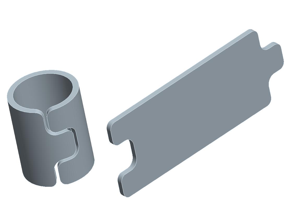
Can someone tell me if its possible to create a rolled sheetmetal part with an overlap. I have a cylindrical ring with interlocking features (see attached sketch), that I want to draw in sheet metal. The part will be lasercut from a piece of tubing and the manufacturer needs a flat geometery, I can't figure out how to create this part in sheet metal.
This thread is inactive and closed by the PTC Community Management Team. If you would like to provide a reply and re-open this thread, please notify the moderator and reference the thread. You may also use "Start a topic" button to ask a new question. Please be sure to include what version of the PTC product you are using so another community member knowledgeable about your version may be able to assist.
- Labels:
-
Sheet Metal Design
- Tags:
- overlap
- Mark as New
- Bookmark
- Subscribe
- Mute
- Subscribe to RSS Feed
- Permalink
- Notify Moderator
Mike,
That's a nice looking model! (I'm curious about what modeling techniques you used.) Have you already tried to convert it to a Sheetmetal part (Applications/Sheetmetal)? I'm wondering how it will handle the unusual aspect ratio of thickness to "flat" width. Also, to create a Flat Pattern, you need some flat reference surface to stay fixed; sometimes in similar situations I have used a little flat tab addition to allow this. I'm assuming your meaning for flat is unrolling the cylinder, not extending what could be seen as rectangular wire. In principle, I don't see why the overlap, per se, should be a problem, but I've never tried it.
David
- Mark as New
- Bookmark
- Subscribe
- Mute
- Subscribe to RSS Feed
- Permalink
- Notify Moderator
Mike,
I was wrong. It's been awhile and I forgot that you only need a straight edge, not a flat surface. Here's an example, part created in Standard mode, converted to Sheetmetal, then flattened.
David

- Mark as New
- Bookmark
- Subscribe
- Mute
- Subscribe to RSS Feed
- Permalink
- Notify Moderator
Hi David,
Thanks for the response. I created my original model as follows:
1. Sketch curve as flat geometery.
2. Swept protrusion of wire cross-section.
3. Spinal bend to roll the part.
The issue is that I want to create the model in the rolled configuration and then have PRO/E convert it to the flat. The actual model I'm creating is much more complex than this and it difficult to draw as a flat. How did you convert your above model into sheetmetal, what did you use as your driving surface?
Thanks
Mike
- Mark as New
- Bookmark
- Subscribe
- Mute
- Subscribe to RSS Feed
- Permalink
- Notify Moderator
Hi Mike,
To convert, I picked Applications/Sheetmetal/Driving Srf, and picked the outside surface of the cylindrical model. After that I picked the straight edge at the end of the "tongue" portion of the model to remain fixed for the Flat Pattern development. Using the Spinal Bend was clever; I've never tried to convert such a part to Sheetmetal, but don't know why it wouldn't work. I created my quick-and-dirty model by creating a cylindrical surface, then Wrapping a Sketch around it which I then used to Trim away the open area, followed by Thicken. You mention further complexity in your model; I'm sure you're aware that you have to keep a constant wall thickness throughout in order to convert successfully. Another thing you might utilize is Unbend; maybe you can create the basics in Standard mode, convert to Sheetmetal, do an Unbend, add some more cuts, then Bend Back. For that, however, I think you will need a flat surface somewhere in your model.
Good luck, and keep me posted!
David
- Mark as New
- Bookmark
- Subscribe
- Mute
- Subscribe to RSS Feed
- Permalink
- Notify Moderator
Hi Mike,
Nice model.
I have small simple tube part I need laser cut and am having a very hard time finding a vender. Can you tell me who is going to cut this part?
My part is ~11mmOD ss tube with .01 wall. Looks medical related.
Regards,
Chris
- Mark as New
- Bookmark
- Subscribe
- Mute
- Subscribe to RSS Feed
- Permalink
- Notify Moderator
Hi Chris,
Here are a few laser cutting companies I've used:
1. Creganna - http://www.cregannatactx.com/
2. Pulse Systems - http://www.pulsesystems.com/
3. Admedes - http://www.admedes.com/
Hope this helps.
Mike
- Mark as New
- Bookmark
- Subscribe
- Mute
- Subscribe to RSS Feed
- Permalink
- Notify Moderator
- Mark as New
- Bookmark
- Subscribe
- Mute
- Subscribe to RSS Feed
- Permalink
- Notify Moderator
Mike,
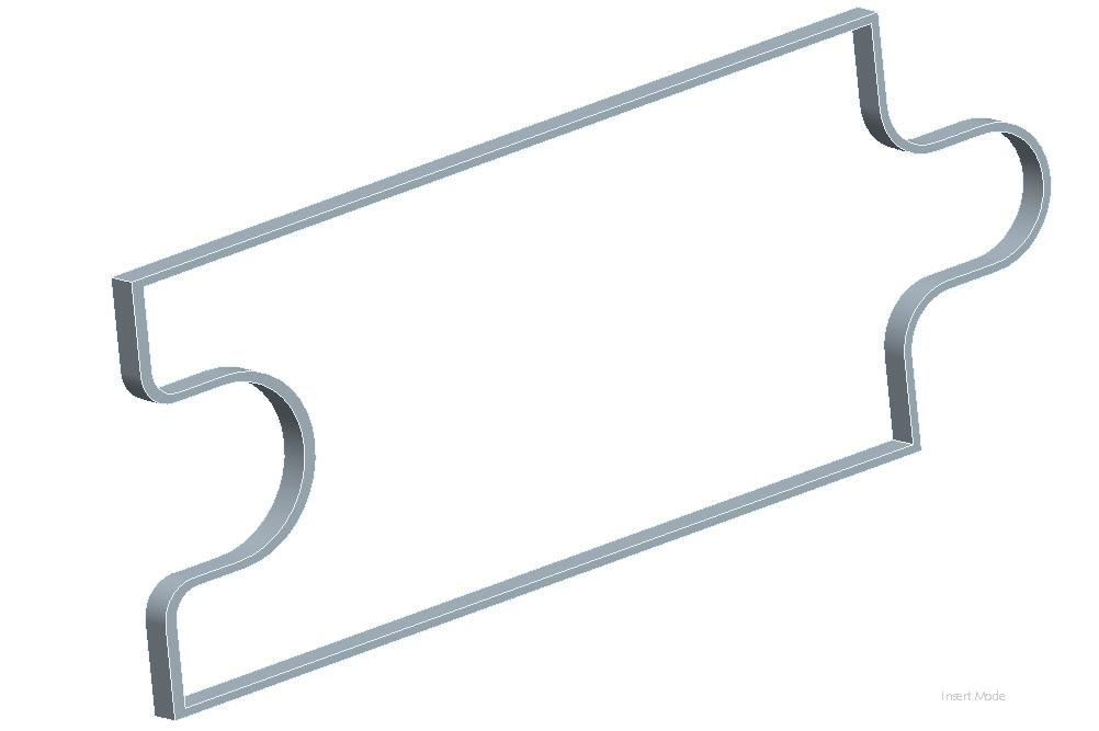
This also worked, and only a reference edge was necessary for the Unbend.
David


