
Turn on suggestions
Auto-suggest helps you quickly narrow down your search results by suggesting possible matches as you type.
Showing results for
Please log in to access translation
Turn on suggestions
Auto-suggest helps you quickly narrow down your search results by suggesting possible matches as you type.
Showing results for
Community Tip - You can Bookmark boards, posts or articles that you'd like to access again easily! X
- Community
- Creo+ and Creo Parametric
- 3D Part & Assembly Design
- Re: Shift surface problem
Translate the entire conversation x
Please log in to access translation
Options
- Subscribe to RSS Feed
- Mark Topic as New
- Mark Topic as Read
- Float this Topic for Current User
- Bookmark
- Subscribe
- Mute
- Printer Friendly Page
Shift surface problem
Dec 30, 2013
03:36 PM
- Mark as New
- Bookmark
- Subscribe
- Mute
- Subscribe to RSS Feed
- Permalink
- Notify Moderator
Please log in to access translation
Dec 30, 2013
03:36 PM
Shift surface problem
Hi Everyone,
My name is Marc, I'm a french technician (English is not my native langage sorry if I make mistake)
I need your help, because I would like to create a lower offset 10.2 mm from my upper "skin".
I created the shift of the surface without difficulty, but I can not properly shift the "holes".
I get discontinuities and overlaps.
Please find enclosed my ".asm"
PS : I havent create the brace/spacer.
Thank for your help.
Marc
Labels:
- Labels:
-
Surfacing
24 REPLIES 24
Dec 30, 2013
05:32 PM
- Mark as New
- Bookmark
- Subscribe
- Mute
- Subscribe to RSS Feed
- Permalink
- Notify Moderator
Please log in to access translation
Dec 30, 2013
05:32 PM
From what I see, the original surface is problematic, full of gaps, overlaps, etc. It will be difficult to get a clean offset from this without some import surface doctoring and repair. I assume you are working from the same imported geometry?
Jan 01, 2014
08:28 AM
- Mark as New
- Bookmark
- Subscribe
- Mute
- Subscribe to RSS Feed
- Permalink
- Notify Moderator
Please log in to access translation
Jan 01, 2014
08:28 AM
Eric,
Yes, I'm working from the same imported geometry.
Perhaps it would be easier if I create a shift only the skin and create a hole for the lower skin.
To shift the skin, I have no problem, but I do not know how to draw like the original hole.
Regards
Marc
Dec 30, 2013
07:08 PM
- Mark as New
- Bookmark
- Subscribe
- Mute
- Subscribe to RSS Feed
- Permalink
- Notify Moderator
Please log in to access translation
Dec 30, 2013
07:08 PM
Welcome to the forum, Marc.
Your surface features are probably easy enough to create. You can probably use the import model as a guide where you can make sections generate datum curves for use in a revolve sketch for the upper skin. Then you can offset this skin for the lower skin. Then add the remaining features to complete an enclosed quilt (merge the surfaces) and then you can solidify it. Maybe a little bit more work than you anticipated but it will make for a more robust model. If you can break all the references to the import model, all the better.
I didn't look at your model since I don't use RAR compression.
Jan 01, 2014
08:38 AM
- Mark as New
- Bookmark
- Subscribe
- Mute
- Subscribe to RSS Feed
- Permalink
- Notify Moderator
Please log in to access translation
Jan 01, 2014
08:38 AM
Antonius,
Thank you for the detailed answer, but with my medium english and Creo level, can you give me more information ?
Do you mean I have to create the skin shift first and then create the hole ? (Because I can create the shape I want for the lower hole)
By "If you can break all the references to the import model, all the better."
Do you mean it's better to brake all the references to create the lower skin (and hole) ?
How can I send you my model ?
Regards
Marc
Jan 01, 2014
03:53 PM
- Mark as New
- Bookmark
- Subscribe
- Mute
- Subscribe to RSS Feed
- Permalink
- Notify Moderator
Please log in to access translation
Jan 01, 2014
03:53 PM
It is highly likely that you can make the solid part directly with some additional features like the hole as a separate feature. Some operations are easier to do with surfacing but for what you are making, I don't think this is necessary.
I prefer to not have dependencies to external models or even the imported file reference. By dependency, I mean that the import model is used as an association in a subsequent sketch. It really depends on how closely you have to follow the original part and there is no other way to make an exact duplicate.
If you use a ZIP compression (without RAR) I can probably open it if it is a full version of any Pro-E file and the import file is included.
Jan 02, 2014
04:41 PM
- Mark as New
- Bookmark
- Subscribe
- Mute
- Subscribe to RSS Feed
- Permalink
- Notify Moderator
Please log in to access translation
Jan 02, 2014
04:41 PM
Antonius,
Thank you for your answers.
I don't have to follow the original part to draw the lower skin.
Please find below my model (without RAR compression)
(I don't how to create the lower hole, can you help me ?)
http://files.engineering.com/getfile.aspx?folder=87e8e53b-5734-4729-8dc9-3cb3ad7c54e1&file=Pro_E.zip
Regards
Marc
Jan 01, 2014
08:26 AM
- Mark as New
- Bookmark
- Subscribe
- Mute
- Subscribe to RSS Feed
- Permalink
- Notify Moderator
Please log in to access translation
Jan 01, 2014
08:26 AM
First of all I wish you a happy new year !
Thank you for your quick responses, with the holiday season I could not answer you earlier.
Jan 02, 2014
05:43 PM
- Mark as New
- Bookmark
- Subscribe
- Mute
- Subscribe to RSS Feed
- Permalink
- Notify Moderator
Please log in to access translation
Jan 02, 2014
05:43 PM
Marc, I was able to get your model. You cannot put holes in surfaces so you have to use the extrude feature with the remove material option. I also see a missing bottom in one of the 3 recesses. You can fill that with a "fill" feature and then use the Merge feature to join the fill feature to your import feature.
Jan 03, 2014
06:15 AM
- Mark as New
- Bookmark
- Subscribe
- Mute
- Subscribe to RSS Feed
- Permalink
- Notify Moderator
Please log in to access translation
Jan 03, 2014
06:15 AM
Antonius,
Thanks again for your quick and complete answer.
I'll will try to follow your advices to draw this afternoon.
I understand what you say, but (as a Creo rookie) I'm not sure of wich function I have to use on Creo to do it.
For example I don't know where I can find the "remove material option". (but google is my friend)
Maybe it's ask too much, but can you draw something on my model, it will be easier for me to translate the function.
PS : I don't know if you received my answer on 2 janv. 2014 13:41, because it's still been moderating.
Regards
Marc
Jan 03, 2014
06:16 AM
- Mark as New
- Bookmark
- Subscribe
- Mute
- Subscribe to RSS Feed
- Permalink
- Notify Moderator
Please log in to access translation
Jan 03, 2014
06:16 AM
If you don't get it my latest version without RAR compression.
http://files.engineering.com/getfile.aspx?folder=87e8e53b-5734-4729-8dc9-3cb3ad7c54e1&file=Pro_E.zip
Marc
Jan 03, 2014
12:50 PM
- Mark as New
- Bookmark
- Subscribe
- Mute
- Subscribe to RSS Feed
- Permalink
- Notify Moderator
Please log in to access translation
Jan 03, 2014
12:50 PM
With many features, you have the option to create material or remove material with this icon: 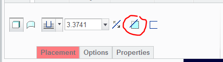
Jan 06, 2014
03:44 AM
- Mark as New
- Bookmark
- Subscribe
- Mute
- Subscribe to RSS Feed
- Permalink
- Notify Moderator
Please log in to access translation
Jan 06, 2014
03:44 AM
Hello,
I have find the advanced editor (thank you Antonius) to post my latest Creo version (zip without winrar).
There is a plan to define the length of the hole, and 3 axis for the screw.
Please find enclosed the model.
Can you help me to draw the hole with this information ?
Regards
Marc
Jan 08, 2014
04:48 PM
- Mark as New
- Bookmark
- Subscribe
- Mute
- Subscribe to RSS Feed
- Permalink
- Notify Moderator
Please log in to access translation
Jan 08, 2014
04:48 PM
Sorry for the delay, Marc, but I have been out of town and could not get back to the conversation.
I find that the skin model you have for the upper skin is very poorly defined and Creo is having trouble healing it. Again, I am no expert on the import data doctor, but in general, it keeps failing to thicken or offset consistently. Someone else may have better luck with it. In theory, you should be able to do a simple 2mm thickening and create the hole feature. I find the IDD very frustrating!
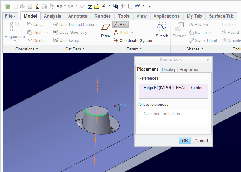
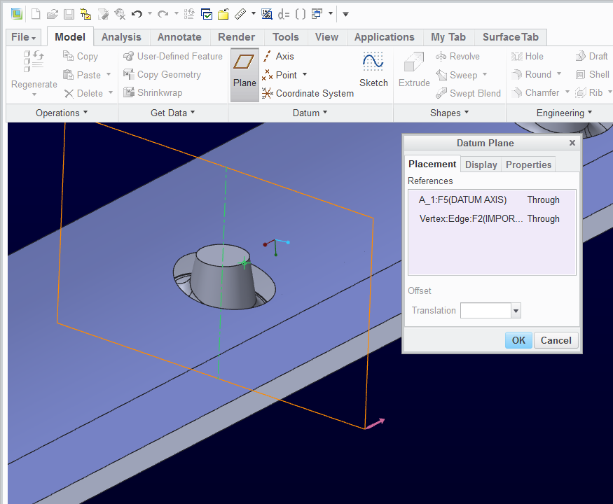
However, to get back on subject, the arcs in the bottom of the upper skin model are a semi-circle by definition. Therefore, you can create an axis on each of the bolt recesses by simply clicking on the arc. There are also endpoints (vertices) on the arcs where you can pick 3 vertices and define a plane (or the axis and 1 vertex). On this you can define a sketch you can revolve to make the feature you are looking for.
Here are some images as to what you can do:
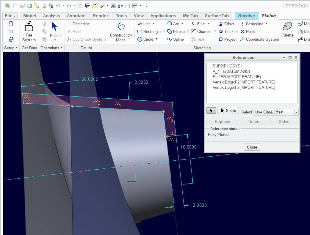
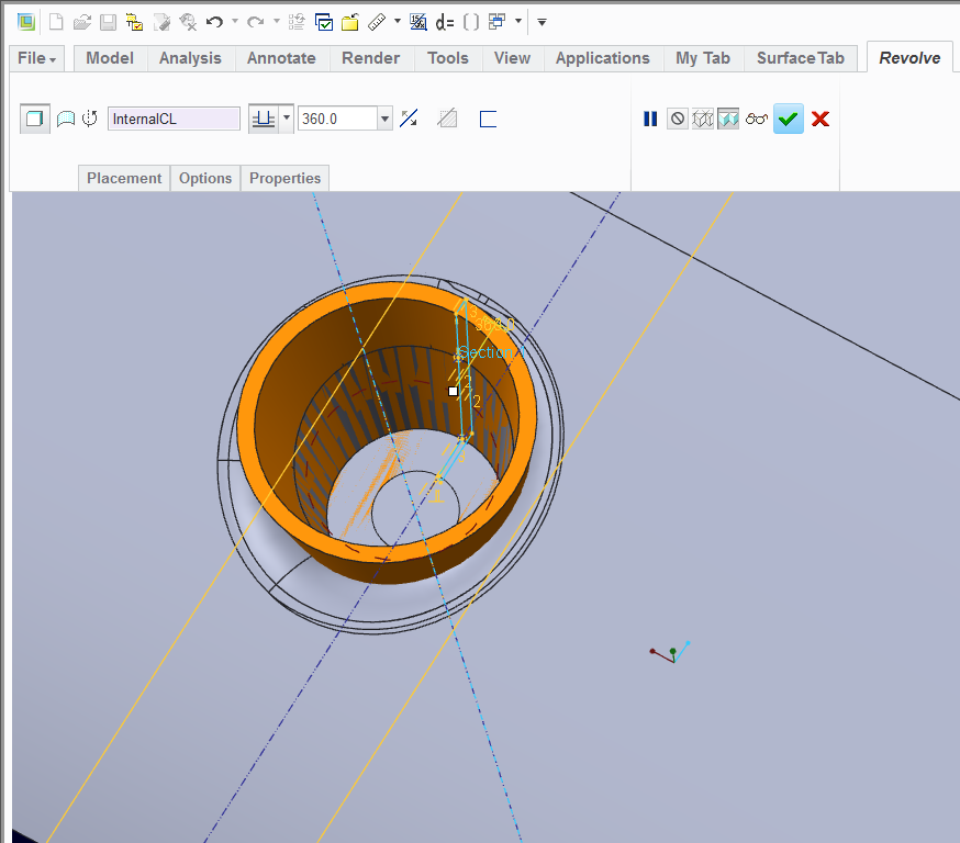
Again, I am not sure what you are looking for as an end result. Just know that there is limited interaction between solid features and surface feature. If you need to blend this somehow, I recommend working with surfaces but the errors in the original import model will give problems with the solidify feature or thicken feature.
Jan 08, 2014
07:21 PM
- Mark as New
- Bookmark
- Subscribe
- Mute
- Subscribe to RSS Feed
- Permalink
- Notify Moderator
Please log in to access translation
Jan 08, 2014
07:21 PM
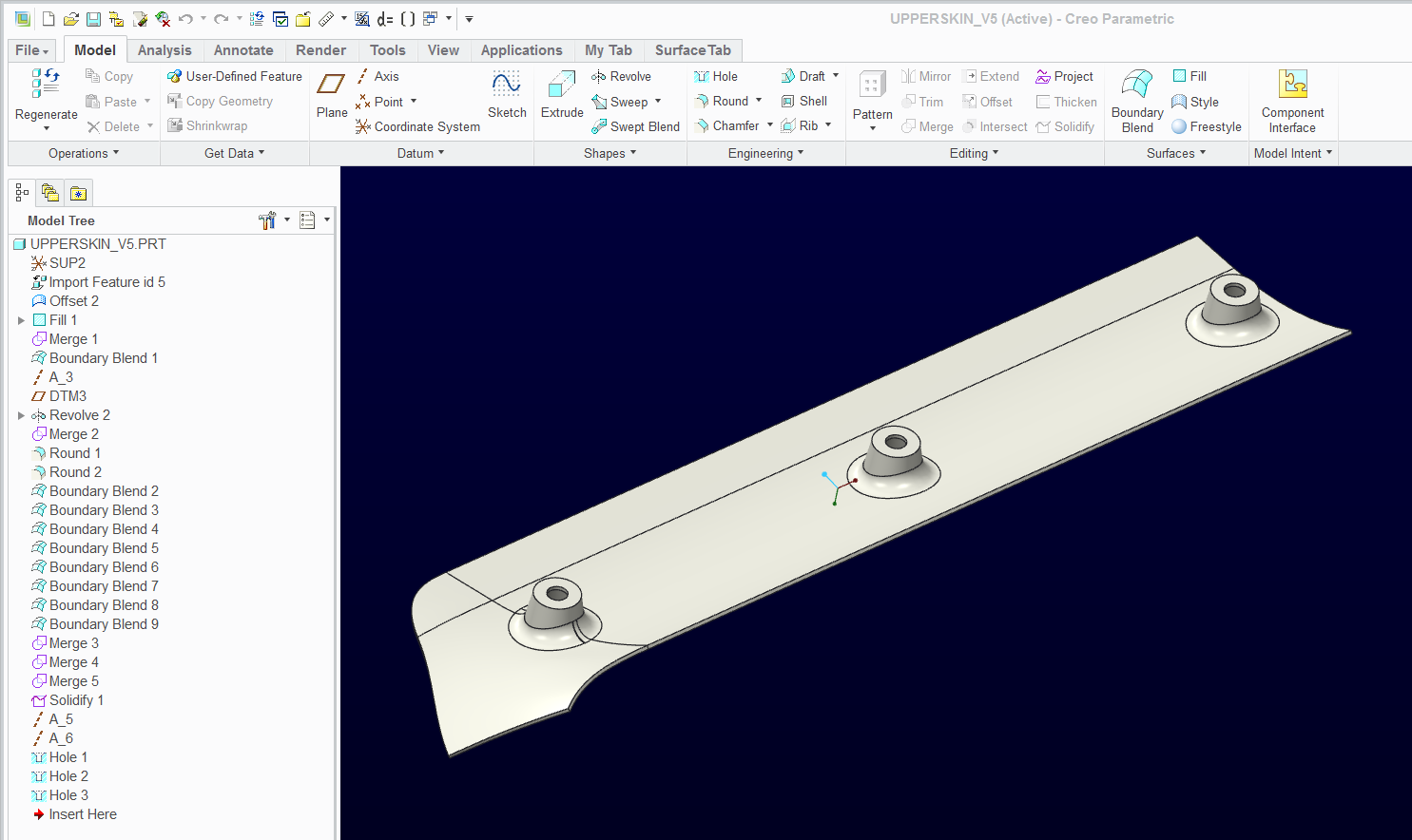
This was certainly a lot more work than I would have ever anticipated with the IDD.
I used a combination of IDD fixes and surface removals and replaced them with native Creo features.
Don't ask me how I got the things to work in the IDD because I honestly do not know. Removing the 2 fillets (rounds) and trimming the surfaces together were done in IDD. Fixing the one corner somehow got fixed with IDD.
I had to fix a sliver in the 3rd fillet with a boundary blend. And I had to create the edges with individual boundary blends. Subsequent merge features finally closed the entire volume to allow the solidify to work.
I used the technique I described above for creating axes for the hole features.
I have attached the file in Creo 2.0 full version and a STEP file. In some cases, I would even opt to use a step version in my Creo session just to "lock" the file from failing in the future.
Jan 09, 2014
10:53 AM
- Mark as New
- Bookmark
- Subscribe
- Mute
- Subscribe to RSS Feed
- Permalink
- Notify Moderator
Please log in to access translation
Jan 09, 2014
10:53 AM
Thank you very much for these very detailed explanation ! ! !
I just saw your message, and I try to follow your method right now, and I'll let you know.
I still have to redraw the cone/hole of the lower skin.
If you have a moment to explain.
Marc
Jan 09, 2014
11:09 AM
- Mark as New
- Bookmark
- Subscribe
- Mute
- Subscribe to RSS Feed
- Permalink
- Notify Moderator
Please log in to access translation
Jan 09, 2014
11:09 AM
Can you open the part file I added to the previous post? You can roll the part back to see where I created the additional features. You would do something very similar for the lower skin.
Jan 13, 2014
11:28 AM
- Mark as New
- Bookmark
- Subscribe
- Mute
- Subscribe to RSS Feed
- Permalink
- Notify Moderator
Please log in to access translation
Jan 13, 2014
11:28 AM
Hello,
Sorry for the delay, I did not have access to internet.
Thanks again for all the time you spent for me.
Yes, I can open your creo file, and see how you redraw the cone, I have follow step by step your method. (Thanks you, it would have been impossible for me without this file)
But (sorry for being a rookie), I don't know how to redraw the first shape of the cone/hole (when I start with the lower skin http://communities.ptc.com/photos/5030).
Regards
Marc
Jan 14, 2014
06:47 PM
- Mark as New
- Bookmark
- Subscribe
- Mute
- Subscribe to RSS Feed
- Permalink
- Notify Moderator
Please log in to access translation
Jan 14, 2014
06:47 PM
Try an offset from the solid file I provided. You should be able to do the offset including the rounds.
To fill in two of the rounds is not a problem with a simply extrude of the edge.. However, the integration of two surfaces for the 3rd is little more tricky.
I have the original offset at 10.2mm form the original surface. Is this still the case and is this also a 2mm thick part making the "inside" 12.2mm from the original surface?
Jan 16, 2014
12:33 PM
- Mark as New
- Bookmark
- Subscribe
- Mute
- Subscribe to RSS Feed
- Permalink
- Notify Moderator
Please log in to access translation
Jan 16, 2014
12:33 PM
Hello,
Thanks again for your help !
Yes, this is also a 2 mm thick part making the "inside" 12.2mm from the original surface.
I have tried different offset options. Do you think the picture enclosed is the best result I can have ?
Regards
Marc
Jan 16, 2014
02:48 PM
- Mark as New
- Bookmark
- Subscribe
- Mute
- Subscribe to RSS Feed
- Permalink
- Notify Moderator
Please log in to access translation
Jan 16, 2014
02:48 PM
The very small quadrant of the import surface is the biggest problem. I have not found a good way to to get this to be reliable.
Once I have a closed surface profile, I would consider working with new Creo surfaces to create the hole details using a revolve feature. You can then merge these features into a single quilt and provide a fillet (round) of whatever radius you desire. You will also not need the 10.2mm offset for the outside of the bosses.
Have a look at Independent Geometry un Get Data. This may help in re-creating the original import surfaces without the holes.
Jan 23, 2014
04:17 PM
- Mark as New
- Bookmark
- Subscribe
- Mute
- Subscribe to RSS Feed
- Permalink
- Notify Moderator
Please log in to access translation
Jan 23, 2014
04:17 PM
Hello,
Sorry to answer so late.
If I well understand, I have to use the new cone and the new surface you created (upperskinV5) to draw my lower skin (offset 10.2mm).
I'm sorry, but it's hard for me to make a parallel between the technical terms and functions in Creo.
Can you send me a example with a upper skin and a lower skin ?
Have a nice day.
Marc
Jan 23, 2014
05:20 PM
- Mark as New
- Bookmark
- Subscribe
- Mute
- Subscribe to RSS Feed
- Permalink
- Notify Moderator
Please log in to access translation
Jan 23, 2014
05:20 PM
Marc, I did try to work with these surfaces some more. Not having much luck with IDD, the surfaces are very problematic.
Your assumptions are correct. I am suggesting making a good inner skin without the holes and recreate the "cups" with new geometry. The problem is trying to close up the hole where the transition is.
Can you request new import features that may be higher quality data? The 4 "panels" of the surface shape simply are not meshing right and I cannot seem to get IDD to solve it so that a reliable offset can be generated.
If you can get a new import file, see if they can provide it without the rounds along the recessed "cups". Even better, can they provide the native surface prior to the trimming of the edges. I am assuming you want to create your edges anyway and extending these for your purposes may be difficult or in the least, limiting.
Typically, industrial design people provide boundary surfaces to designers without features and often extend beyond the edges. This would be a better place to start from.
Jan 26, 2014
08:09 AM
- Mark as New
- Bookmark
- Subscribe
- Mute
- Subscribe to RSS Feed
- Permalink
- Notify Moderator
Please log in to access translation
Jan 26, 2014
08:09 AM
Tom,
Thanks again for your answer.
My original part is a ".step", because the part has been created on CATIA.
But I will try to send you another step, maybe it will be better.
Marc
Jan 05, 2014
07:08 AM
- Mark as New
- Bookmark
- Subscribe
- Mute
- Subscribe to RSS Feed
- Permalink
- Notify Moderator
Please log in to access translation
Jan 05, 2014
07:08 AM
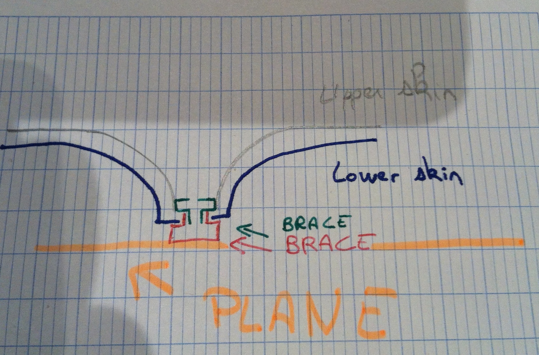
Hello,
I have put two pictures to try to explain you what I like to do.
I think I'm missing the method to draw the hole of the lower skin. Can you help me to draw this hole ? ( I don't need to get the same dimension than the upper skin, but just something who looks like).
http://communities.ptc.com/photoAlbums/1705
The wall thickness and the sidewalls of the cone is 2 mm. (the real thickness will not be constant as it is a thermoplastic)
Regards
Marc


.JPG)