
Turn on suggestions
Auto-suggest helps you quickly narrow down your search results by suggesting possible matches as you type.
Showing results for
Please log in to access translation
Turn on suggestions
Auto-suggest helps you quickly narrow down your search results by suggesting possible matches as you type.
Showing results for
Community Tip - New to the community? Learn how to post a question and get help from PTC and industry experts! X
- Community
- Creo+ and Creo Parametric
- 3D Part & Assembly Design
- Showing Dimensions for Mirrored Features
Translate the entire conversation x
Please log in to access translation
Options
- Subscribe to RSS Feed
- Mark Topic as New
- Mark Topic as Read
- Float this Topic for Current User
- Bookmark
- Subscribe
- Mute
- Printer Friendly Page
Showing Dimensions for Mirrored Features
May 13, 2020
04:35 PM
- Mark as New
- Bookmark
- Subscribe
- Mute
- Subscribe to RSS Feed
- Permalink
- Notify Moderator
Please log in to access translation
May 13, 2020
04:35 PM
Showing Dimensions for Mirrored Features
Hello,
I frequently try and streamline my workload in Creo through the use of mirroring. Why do the same work twice when you can leverage the mirror feature? This saves time on the front-end modeling, but catches up with you on the back-end detailing in the sense that it does not appear to be possible to show dimensions of a mirrored feature in a drawing. How then do you articulate that symmetry to the fabricator unless you add dimensions, which contradicts best practices and opens up the risk of dimensions "falling off drawings"?
I prefer to model holes using extruded cuts for this reason; that is, I can mirror the hole features in a sketch and tailor my dimensioning scheme in the sketch so that it can be shown in the drawing downstream. However, this contradicts best practices because you should be using the hole tool for holes. Everyone seeing the pattern here?
Labels:
- Labels:
-
2D Drawing
5 REPLIES 5
May 13, 2020
05:28 PM
- Mark as New
- Bookmark
- Subscribe
- Mute
- Subscribe to RSS Feed
- Permalink
- Notify Moderator
Please log in to access translation
May 13, 2020
05:28 PM
Hey wbottis,
I think there are a couple ways to go about this.
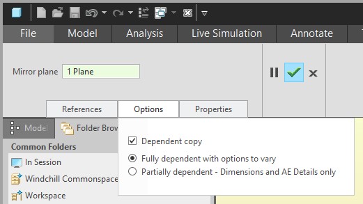
You can use Mirror > Options > Fully dependent with options to vary. This will show dimensions for both sets of holes. If you make change to the mirrored hole, it will prompt to ask you if you want to make it independent (if you want to keep the mirrored relation, you always have to change the original hole dimensions).
You can use Point Patterns. These aren't truly mirrored, but I've found they are handy. Create a sketch on a surface to locate your holes. Create geometry points in the sketch and close it. Create a hole and place it on the surface and the point. Pattern the hole using a Point Pattern and select your sketch. You can use relations to make it mirrored, but that does add some work where mirror relates them for free.
Hope that helps, let me know if there was something I missed.
Cheers,
Nick
May 14, 2020
07:14 AM
- Mark as New
- Bookmark
- Subscribe
- Mute
- Subscribe to RSS Feed
- Permalink
- Notify Moderator
Please log in to access translation
May 14, 2020
07:14 AM
You can use Mirror > Options > Fully dependent with options to vary. This will show dimensions for both sets of holes. If you make change to the mirrored hole, it will prompt to ask you if you want to make it independent (if you want to keep the mirrored relation, you always have to change the original hole dimensions).
This almost gets you there except you want to show the locating dimensions from one hole to the other hole on the other side of the center plane, not both relative to the center plane. The latter just clutters the drawing for the fabricator. See attached picture.
You can use Point Patterns. These aren't truly mirrored, but I've found they are handy. Create a sketch on a surface to locate your holes. Create geometry points in the sketch and close it. Create a hole and place it on the surface and the point. Pattern the hole using a Point Pattern and select your sketch. You can use relations to make it mirrored, but that does add some work where mirror relates them for free.
This was my approach before posting. I don't think you need to deal with relations because you can mirror your sketch features and then dimension across the centerline accordingly within the sketch itself. It's still a workaround in my opinion. The hole pattern tool should be tailored to do what I have described originally. That is the right way to do it and PTC has had plenty of time to implement this over the years. It's time to implement it.
May 14, 2020
12:16 PM
- Mark as New
- Bookmark
- Subscribe
- Mute
- Subscribe to RSS Feed
- Permalink
- Notify Moderator
Please log in to access translation
May 14, 2020
12:16 PM
Ahh, I understand what you mean now. Yes, that would be a handy function if it was added, sort of how we can switch from radius to diameter fairly easily. Typically we would do 2X .50" instead of straddling the centerline with 1.00" dimension, but I definitely see value in that way as well. And you right about the relations, would be much easier to use mirror or constraints in the sketch.
May 13, 2020
08:28 PM
- Mark as New
- Bookmark
- Subscribe
- Mute
- Subscribe to RSS Feed
- Permalink
- Notify Moderator
Please log in to access translation
May 13, 2020
08:28 PM
Depending on your drawing standard for interpretation (i.e. ANSI Y14.5) you should be able to use centerlines or datums to denote part symmetry in a 2D drawing or MBD features. If the feature is mirrored then it is symmetric about the mirror plane. You can then add a suffix to any dim that is using the mirror plane (centerline) as a reference.
You can create the centerlines in the model as annotation features and I suggest this approach rather than using draft entities in a drawing.
As an example lets say you have two holes that are 1" off the centerline of the part you would add a "2X" suffix for the location dims used for the hole. You only need the one dimension to locate both holes on each axis so 2 dimensions would locate both holes in the same plane (view).
You can also create an annotation dimension that spans the mirror plane as required (MBD) in the model.
If you need to consider tolerance stack ups then there is a symmetry GDT control symbol in ANSI Y14.5 which must be used in conjunction with GDT reference frame (datums). Using the centerline as a dimension reference may not always meet spec or drawing standard.
========================================
Involute Development, LLC
Consulting Engineers
Specialists in Creo Parametric
Involute Development, LLC
Consulting Engineers
Specialists in Creo Parametric
Apr 12, 2021
10:19 AM
- Mark as New
- Bookmark
- Subscribe
- Mute
- Subscribe to RSS Feed
- Permalink
- Notify Moderator
Please log in to access translation
Apr 12, 2021
10:19 AM
We currently use ASME Y14.5 for our drawings as well. ASME removed concentricity & symmetry symbols in the latest version of their standard and replaced them with existing symbols. This was because these two are hard to measure and can for the most part be replaced with existing symbols. To indicate symmetry, I believe we're supposed to switch over to True Position. To indicate coaxial/concentricity, there are a few symbols you can use. True Position, Runout/Total Runout, and Profile of a Surface (just depends on the application/how tight the tolerances need to be). I don't know for sure, but I think PTC kept the old symbols for legacy drawings.
But you are correct, from ASME Y14.5 point of view, I don't think you can use centerlines as a datum feature simulator/reference frame, I believe you need to use a physical feature like a hole, boss, surface, etc.


