
Turn on suggestions
Auto-suggest helps you quickly narrow down your search results by suggesting possible matches as you type.
Showing results for
Please log in to access translation
Turn on suggestions
Auto-suggest helps you quickly narrow down your search results by suggesting possible matches as you type.
Showing results for
Community Tip - Visit the PTCooler (the community lounge) to get to know your fellow community members and check out some of Dale's Friday Humor posts! X
- Community
- Creo+ and Creo Parametric
- 3D Part & Assembly Design
- Re: Slot on circle surface
Translate the entire conversation x
Please log in to access translation
Options
- Subscribe to RSS Feed
- Mark Topic as New
- Mark Topic as Read
- Float this Topic for Current User
- Bookmark
- Subscribe
- Mute
- Printer Friendly Page
Slot on circle surface
Oct 24, 2016
08:15 AM
- Mark as New
- Bookmark
- Subscribe
- Mute
- Subscribe to RSS Feed
- Permalink
- Notify Moderator
Please log in to access translation
Oct 24, 2016
08:15 AM
Slot on circle surface
Hello,
l have some modeling problem and asking about help. See attached file (Creo 2.0)
l´m modeling slot on circle surface with a problem in transition between flat part and curved part.
Red marked surface doesn´t looke fine ... l think something is wrong in my modeling procces (but what?).
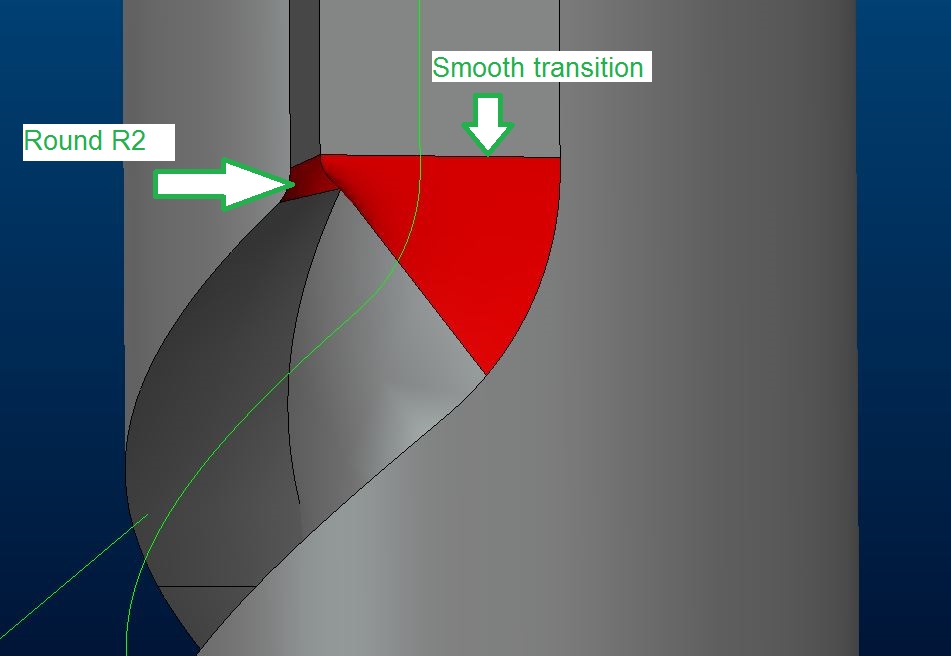
How to model it in order to use round feater on inner edge?
Is my technique correct? (using warp feater)
Thx for guidance
Regards
Milan Bonka
13 REPLIES 13
Oct 24, 2016
09:13 AM
- Mark as New
- Bookmark
- Subscribe
- Mute
- Subscribe to RSS Feed
- Permalink
- Notify Moderator
Please log in to access translation
Oct 24, 2016
09:13 AM
Based on a quick adjustment of the dimensions I'd say your dimensions for the slot are not appropriate for a smooth transition, the technique is fine.
Oct 24, 2016
09:20 AM
- Mark as New
- Bookmark
- Subscribe
- Mute
- Subscribe to RSS Feed
- Permalink
- Notify Moderator
Please log in to access translation
Oct 24, 2016
09:20 AM
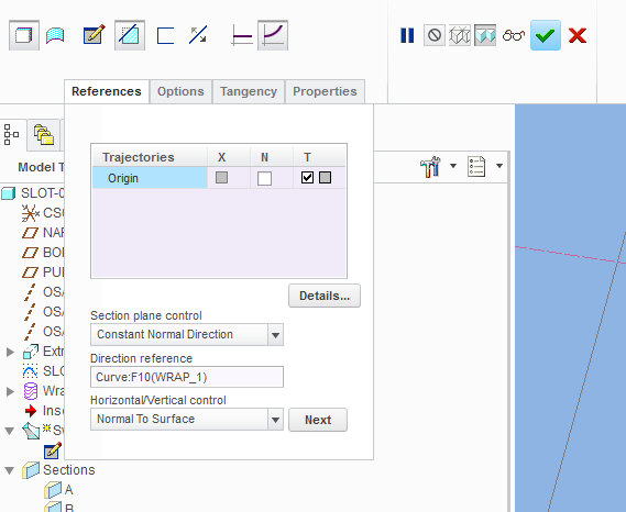
You need to adjust a few controls inside sweep feature.
Have a look on the attached image.
Hope this helps.
Oct 24, 2016
10:51 AM
- Mark as New
- Bookmark
- Subscribe
- Mute
- Subscribe to RSS Feed
- Permalink
- Notify Moderator
Please log in to access translation
Oct 24, 2016
10:51 AM
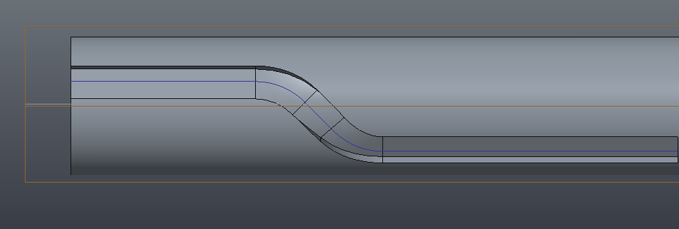
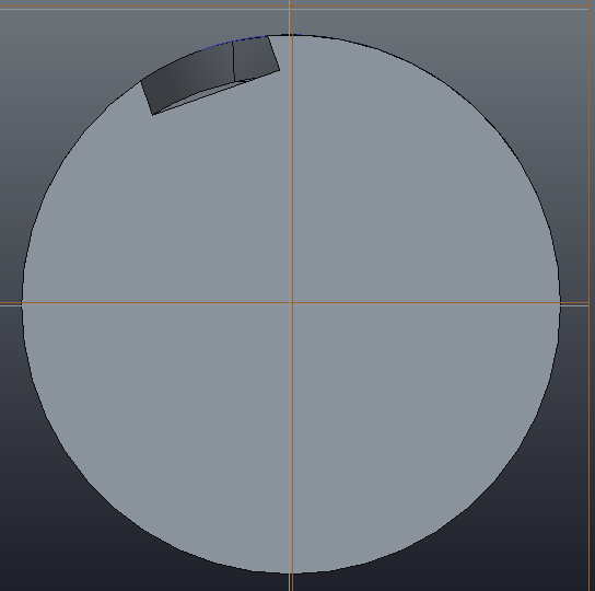
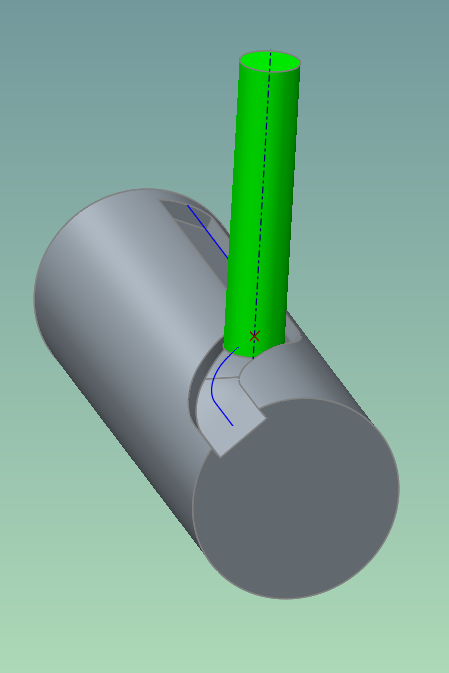
Hi, I have had a little go at doing this feature. I created a sketch plane above the cylinder and sketched a trajectory, this is then projected onto the cylinder. Use a sweep on the end to create the slot profile and project this along your trajectory. I had some issues which you may need to address too, if the included angle is too great it will project around the other side of the cylinder too so don't take it right to the edge. I have attached a couple of screenshots to show what I mean. You shouldn't need to patch any rads in. If you included angle is too great then this may not work (show as about 45 deg. in my example)
Oct 24, 2016
11:52 AM
- Mark as New
- Bookmark
- Subscribe
- Mute
- Subscribe to RSS Feed
- Permalink
- Notify Moderator
Please log in to access translation
Oct 24, 2016
11:52 AM
Keep in mind, a milling cutter will almost always not create the geometry you model in this situation. The deviation from what is modeled will depend on the size of the cutter vs. the modeled geometry, and the actual trajectory of the modeled geometry.
To create the actual "cut" geometry it can be an absolute PITA.
Oct 24, 2016
01:06 PM
- Mark as New
- Bookmark
- Subscribe
- Mute
- Subscribe to RSS Feed
- Permalink
- Notify Moderator
Please log in to access translation
Oct 24, 2016
01:06 PM
In this case, the cut geometry will actually work; because a projected curve curve used as the trajectory, the sweep section's horizontal/vertical orientation will be controlled using the "Normal to surface" option (the surface onto which the trajectory was projected). This means that the cutter axis will always go through the stock axis. And since the section plane will stay normal to the trajectory, such sweep will faithfully represent a cut made by an endmill that moves along the stock axis while the stock is turning.
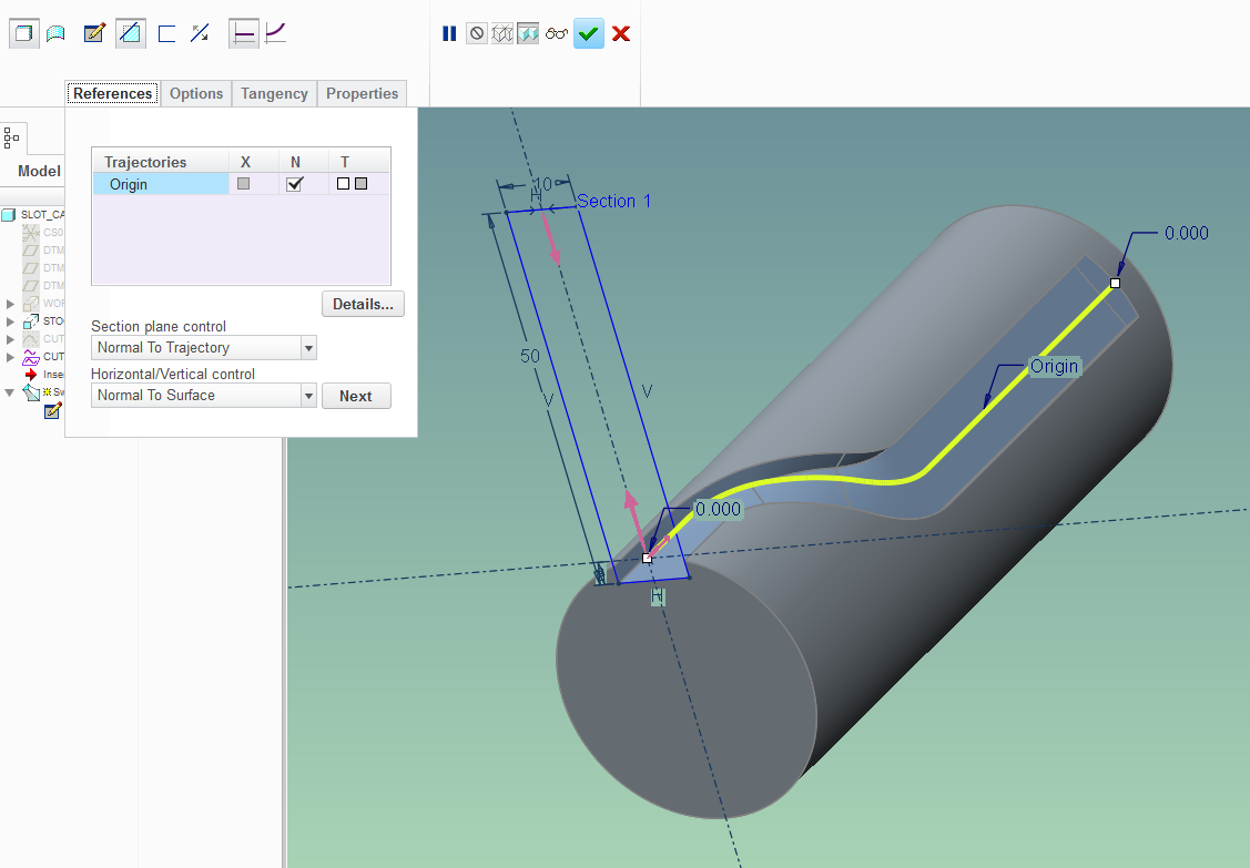
Because of the limitation of the projection curve only working in the 1/2 of the cylindrical surface, using wrapped sketches to generate the trajectory curve might be preferable.
Oct 24, 2016
03:08 PM
- Mark as New
- Bookmark
- Subscribe
- Mute
- Subscribe to RSS Feed
- Permalink
- Notify Moderator
Please log in to access translation
Oct 24, 2016
03:08 PM
Actually, that's totally incorrect. The difference is that a cutting tool is a side-cutting device, and will remove MORE material that your cut, sometimes a LOT more depending on the sweep trajectory (the tighter the curve radii the bigger difference). Take the trajectory and pattern a series of points along it at, say, .010" intervals. Then pattern cylindrical cuts of the cutting tool size at every point and you'll see what I mean.
This is a known issue, and there is at least one thread dedicated to it. 
Oct 24, 2016
05:14 PM
- Mark as New
- Bookmark
- Subscribe
- Mute
- Subscribe to RSS Feed
- Permalink
- Notify Moderator
Please log in to access translation
Oct 24, 2016
05:14 PM
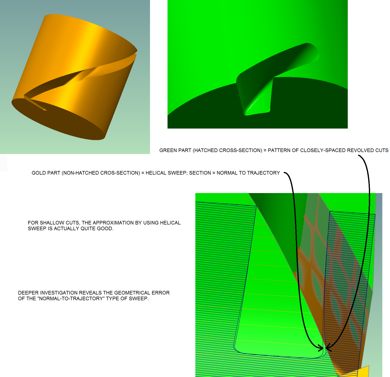
You are totally right Frank. For some reason, I always wrongly thought that for a case where the axis of the endmill is normal to the cylinder it is cutting, the "Normal to trajectory option" produced correct results. I recall a while ago, I wanted to see which option of helical sweep section control (normal to trajectory vs. through axis of revolution) would produce a more faithful representation of an endmill cutting a helical path. For this, I used the very same pattern of cylindrical cuts you suggested (in green below). I saw that the "through axis of revolution" option (in white) was not producing correct geometry, while while the "normal to trajectory" option (in gold, being highlighted below) seemed spot-on:
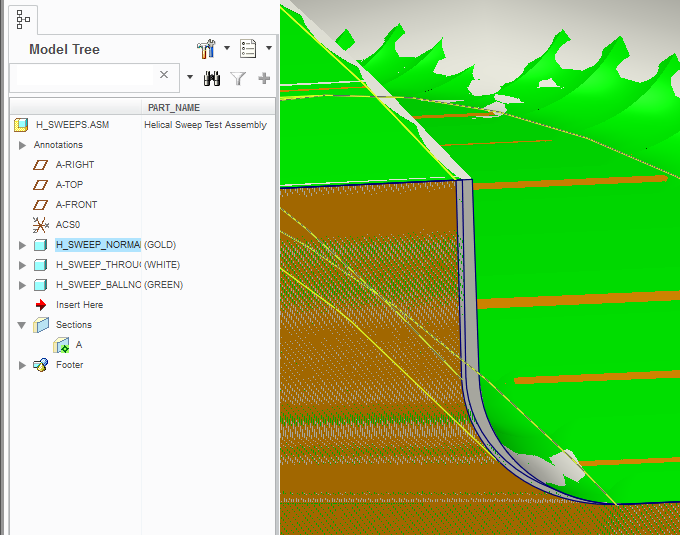
Today I "dug" deeper into the issue and sure enough, the extra tip gouging is easily revealed:
Oct 24, 2016
06:39 PM
- Mark as New
- Bookmark
- Subscribe
- Mute
- Subscribe to RSS Feed
- Permalink
- Notify Moderator
Please log in to access translation
Oct 24, 2016
06:39 PM
It's an easy mistake to make, I did it at first, blindly believing creo did what I WANTED, instead of doing what I TOLD it to do. And the tighter the curves on the trajectory, the more the actual cut is different. Antonius did a lot of great work to create a true cut on, I believe, a globoidal cam? It's because the section of any swept cut is PLANAR, and only cuts as a plane, whereas a cutting tool is cylindrical, and cuts in 3D, if that makes sense.
What we NEED is a "solid body" cut like (but better than), uh, SW has..... 
Oct 24, 2016
07:28 PM
- Mark as New
- Bookmark
- Subscribe
- Mute
- Subscribe to RSS Feed
- Permalink
- Notify Moderator
Please log in to access translation
Oct 24, 2016
07:28 PM
Yeah, you can see from a quick search that Autodesk Inventor also has capabilities that exceed Creo in this area:
https://www.youtube.com/watch?v=Tn5OMml4eDg
We'll see what "3d body sweep" functionality PTC managed to put into Creo 4. While the "beta" didn't have this function, they hinted that the full release would have it.
And it seems that patterning of the "material-removing tool" along its trajectory gets you pretty far along; yeah it's slow but then again this is actually pretty intensive computations going on.
Maybe what's missing is the ability to easily gather the rough edges and "smooth" the result.
Oct 24, 2016
09:28 PM
- Mark as New
- Bookmark
- Subscribe
- Mute
- Subscribe to RSS Feed
- Permalink
- Notify Moderator
Please log in to access translation
Oct 24, 2016
09:28 PM
Look up Antonius's thread, he did some awesome stuff with it.
Oct 24, 2016
09:29 PM
- Mark as New
- Bookmark
- Subscribe
- Mute
- Subscribe to RSS Feed
- Permalink
- Notify Moderator
Please log in to access translation
Oct 24, 2016
09:29 PM
Technically, it's an add-on for Inventor that only handles a specific intersection type with a simple prismatic shape. While it has a nice interface, the process isn't that complicated. What is complicated, and what this doesn't do, is produce analytic or continuously smooth surfaces.
Jan 02, 2017
11:59 AM
- Mark as New
- Bookmark
- Subscribe
- Mute
- Subscribe to RSS Feed
- Permalink
- Notify Moderator
Please log in to access translation
Jan 02, 2017
11:59 AM
According to CS25133 , which is "forward looking information only..."
https://support.ptc.com/appserver/cs/view/solution.jsp?source=subscription&n=CS251133
in Creo 4.0 M020 they plan to add modelling tools for :
- 3D slot milling in a block (cutter axis stays normal to a plane)
- helical slot grinding (grinding wheel axis stays parallel to axis of constant or variable pitch helix)
but sadly not :
- 3D slot milling on a cylinder or solid of revolution (where cutter axis stays normal to cylinder/revolved body axis - as per this discussion thread)
I suppose 2 out of 3 ain't bad, so lets all keep our fingers crossed that they will add the requested feature, as requested, in M030 !
Oct 25, 2016
07:51 AM
- Mark as New
- Bookmark
- Subscribe
- Mute
- Subscribe to RSS Feed
- Permalink
- Notify Moderator
Please log in to access translation
Oct 25, 2016
07:51 AM
Here's a product idea for solid body sweep.


