
Turn on suggestions
Auto-suggest helps you quickly narrow down your search results by suggesting possible matches as you type.
Showing results for
Please log in to access translation
Turn on suggestions
Auto-suggest helps you quickly narrow down your search results by suggesting possible matches as you type.
Showing results for
Community Tip - Did you get called away in the middle of writing a post? Don't worry you can find your unfinished post later in the Drafts section of your profile page. X
Translate the entire conversation x
Please log in to access translation
Options
- Subscribe to RSS Feed
- Mark Topic as New
- Mark Topic as Read
- Float this Topic for Current User
- Bookmark
- Subscribe
- Mute
- Printer Friendly Page
Solidify?
Apr 07, 2015
11:34 AM
- Mark as New
- Bookmark
- Subscribe
- Mute
- Subscribe to RSS Feed
- Permalink
- Notify Moderator
Please log in to access translation
Apr 07, 2015
11:34 AM
Solidify?
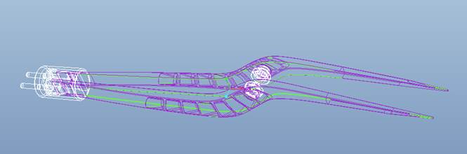
I'm on WF5 M080, I received an IGS file which imported into ProE with no problem. However, when you change it to wireframe, it looks like a bunch of curves and surfaces. Is there a method where I can convert them into solids? I'm not familiar with surfacing so I am reaching out to you gurus.
[cid:image003.jpg@01D07126.BEF57E40]
Calvin
[cid:image003.jpg@01D07126.BEF57E40]
Calvin
14 REPLIES 14
Apr 07, 2015
11:41 AM
- Mark as New
- Bookmark
- Subscribe
- Mute
- Subscribe to RSS Feed
- Permalink
- Notify Moderator
Please log in to access translation
Apr 07, 2015
11:41 AM
do "edit definition" on the imported solid.
when in edit definition mode you can perform some healing routines like a
"zip gaps".
Also you can set the features options to "make solid"
where these features are hidden depends on which version of Pro/E you are
running.
Pete
On Tue, Apr 7, 2015 at 8:34 AM, Ying, Calvin <->
wrote:
> I’m on WF5 M080, I received an IGS file which imported into ProE with no
> problem. However, when you change it to wireframe, it looks like a bunch
> of curves and surfaces. Is there a method where I can convert them into
> solids? I’m not familiar with surfacing so I am reaching out to you gurus.
>
>
>
>
>
>
>
> Calvin
>
Apr 07, 2015
11:48 AM
- Mark as New
- Bookmark
- Subscribe
- Mute
- Subscribe to RSS Feed
- Permalink
- Notify Moderator
Please log in to access translation
Apr 07, 2015
11:48 AM
As long as it is a complete quilt, you can solidify the whole thing (using the solidify command). You need to select the quilt, not the import feature itself, and not a single surface, and then use the command.
If it came in as surfaces, odds are it is because there are missing surface patches, hence why it got exported/imported not solid. You could try to fix missing surface patches using the Import Data Doctor (IDD), but that can be awefully time sonsuming.
It could also be that whoever did the export had it configured to send it as surfaces; you could ask them to send it as a solid and see if they can help.
Another thing to try, make sure you imported as a part. If you import it as an assembly (even in a flat file structure), it may come in as surfaces, too.
Apr 07, 2015
12:01 PM
- Mark as New
- Bookmark
- Subscribe
- Mute
- Subscribe to RSS Feed
- Permalink
- Notify Moderator
Please log in to access translation
Apr 07, 2015
12:01 PM
Calvin,
The purple you see is a "quilt" - that is a collection of surfaces that are
joined together at their edges. When all of the edges are perfectly joined,
the edges are displayed as purple. When the edge is not attached to another
surface - that is, hanging out in space (like the lip of a bucket) - that
open edge is displayed as pink. If you imagine the quilt being able to hold
liquid, it can become a solid. But if the model has any open (pink) edges,
the solid will "leak out" and the Solidify command will not work. If the
import is your first feature, and all edges are purple, it should solidify
automatically.
I think the "right" way to do it is using Import Data Doctor (Pete's
reference to "zip gaps". Auto zip gaps works about 1% of the time in my
experience - it is worth the try, but don't hold your breath.) This is a
cumbersome and non-intuitive tool that will help you find gaps and stitch
them together.
Depending on your need for an accurate model (i.e. if it is going to
tooling, you may need a perfect solid; if it is for a presentation or to
design around, a hack job might work.)
Here are some ideas other than IDD and Zip Gaps:
- increase your model accuracy and THEN import the IGS.
-get the vendor to send you an SAT or STP or X_T - all of these can be
imported by Pro/E and have varying results. (McMaster Carr models are always
better imported as SAT files for me.)
-If you can find the pink edges and there are not too many of them, you can
plug the hole with a solid - I have successfully solidified imported
geometry by creating a tiny protrusion that surrounds the pink edges -
plugging the gaps with a solid "holds water" just as well as creating
perfectly aligned surfaces.
-if you have access to Solidworks - or some other CAD package, try importing
it with the other CAD and exporting it various ways and re-importing those
into Pro/E. This works very often as well.
Occasionally, I will receive a model that will not behave and I have to go
back to the person who sent it and beg for help - always my last resort.
Let us know how you end up!
-Nate
Apr 07, 2015
12:17 PM
- Mark as New
- Bookmark
- Subscribe
- Mute
- Subscribe to RSS Feed
- Permalink
- Notify Moderator
Please log in to access translation
Apr 07, 2015
12:17 PM
if you set your colors to "pre-wildfire" you can get the open quilt edges
as a nice contrasting color that may be easier to see.
Also, per Nate's suggestion, adjusting model accuracy sometimes allows
imports to solidify/stitch. Sometimes it makes it worse.
If you need to the import as just a space claim for interference checks,
etc; I have even simply, minimally cut away "trouble areas" of the quilt
via small extruded cylinders quilts - merged to the master quilt, then
solidifying that resultant quilt.
Pete
Apr 07, 2015
12:45 PM
- Mark as New
- Bookmark
- Subscribe
- Mute
- Subscribe to RSS Feed
- Permalink
- Notify Moderator
Please log in to access translation
Apr 07, 2015
12:45 PM
I’m partially color blind (thanks, mom). I can see all colors, just like you, however I cannot always discern what color family (range, hue etc.) I’m looking at. For me, I ALWAYS use the “pre-wildfire” color scheme with a black background. When dealing with surfaces, which I use daily, the pre-wildfire colors show up as, Magenta and Yellow. For me, that makes it easy(er) to spot the guilty offender.
From time to time, I have also removed small problemed surfaces and just patched them with a boundary blend or some other method, just to make the quilt “water tight”, so that I could solidify the model. Although I have done it this way in the past, I first try to fix it in, Import Data Doctor. I have had varying degrees of success with IDD, but like was previously mentioned, IDD is not very intuitive and there is very little in the way of assistance available on the internet. It’s mostly hit or miss, but it is worth a try. Sometimes you get terrific results.
Something else you may want to look at is… are there any small corner or sharp intersecting surfaces that twist or overlap at ANY point in the model? If you do, then you will NEVER be able to solidify the model. You will be forced to clean up the file with IDD, or perhaps the file you received from your customer/vendor has a problem and you might need to go back to them and have them correct the problem and re-send the file.
At the company I work for, we are fortunate to have one seat of SolidWorks, one seat of UG and several seats of Inventor, along with many seats of Creo. We have found that importing the offending files into SW, UG or Inventor and then exporting the file as a “new” STEP or x_t file or even as a CATIA file and re-reading the new file into Pro/E – Creo will sometimes generate a solid file that we can work with. Many times, the competitor CAD programs do a better job translating STEP and IGES files than does Creo. One side note, the CATIA translator in Creo works very well and will almost always import CATIA files as solids on the first shot.
Bob Schwerdlin
Sr. Design Engineer
Dukane Corp.
2900 Dukane Dr.
St. Charles, IL 60174 USA
630-679-1941 direct
-
www.dukane.com/us
Apr 07, 2015
01:08 PM
- Mark as New
- Bookmark
- Subscribe
- Mute
- Subscribe to RSS Feed
- Permalink
- Notify Moderator
Please log in to access translation
Apr 07, 2015
01:08 PM
The Find Tool can also find any of these "pink" edges that need to be corrected, in case they're not easily visible to the naked eye.
Look for: Edge, Look by: Edge, Attribute tab > Type radio button > Value menu > One-sided
In Reply to Bob Schwerdlin:
I’m partially color blind (thanks, mom). I can see all colors, just like you, however I cannot always discern what color family (range, hue etc.) I’m looking at. For me, I ALWAYS use the “pre-wildfire” color scheme with a black background. When dealing with surfaces, which I use daily, the pre-wildfire colors show up as, Magenta and Yellow. For me, that makes it easy(er) to spot the guilty offender.
From time to time, I have also removed small problemed surfaces and just patched them with a boundary blend or some other method, just to make the quilt “water tight”, so that I could solidify the model. Although I have done it this way in the past, I first try to fix it in, Import Data Doctor. I have had varying degrees of success with IDD, but like was previously mentioned, IDD is not very intuitive and there is very little in the way of assistance available on the internet. It’s mostly hit or miss, but it is worth a try. Sometimes you get terrific results.
Something else you may want to look at is… are there any small corner or sharp intersecting surfaces that twist or overlap at ANY point in the model? If you do, then you will NEVER be able to solidify the model. You will be forced to clean up the file with IDD, or perhaps the file you received from your customer/vendor has a problem and you might need to go back to them and have them correct the problem and re-send the file.
At the company I work for, we are fortunate to have one seat of SolidWorks, one seat of UG and several seats of Inventor, along with many seats of Creo. We have found that importing the offending files into SW, UG or Inventor and then exporting the file as a “new” STEP or x_t file or even as a CATIA file and re-reading the new file into Pro/E – Creo will sometimes generate a solid file that we can work with. Many times, the competitor CAD programs do a better job translating STEP and IGES files than does Creo. One side note, the CATIA translator in Creo works very well and will almost always import CATIA files as solids on the first shot.
Bob Schwerdlin
Sr. Design Engineer
Dukane Corp.
2900 Dukane Dr.
St. Charles, IL 60174 USA
630-679-1941 direct
-
www.dukane.com/us
Apr 07, 2015
01:49 PM
- Mark as New
- Bookmark
- Subscribe
- Mute
- Subscribe to RSS Feed
- Permalink
- Notify Moderator
Please log in to access translation
Apr 07, 2015
01:49 PM
Thanks to all who have replied.
SUMMARY:
* Purple colors = quilt & joined together (Good thing)
* Green color= open gap (bad thing) You can change the color scheme to pre-WF (pink - tough to see with purple)
WF5 Import doctor is not user friendly and very tedious to use. I have no clue what I'm doing.
I have Solidworks 2014 (which I am not a solidworks user), only use to convert to STP/IGES. I retrieve the model using SW and the get the import error which put me in the fix mode. Using the Fix, Delete, Heal, face and Close gap etc I was able to remove all the errors. However, when I export the file to STP and import it to WF5 (accuracy .0001) I am getting different Green lines. Since I have Creo 3 loaded, I figure the Unite Technology would be a better version to import the model. No dice....therefore I give up. I was just trying to help an user with this issue, and I already spent more time than I wanted. However I did learn a lot from the replies 🙂
Apr 07, 2015
01:57 PM
- Mark as New
- Bookmark
- Subscribe
- Mute
- Subscribe to RSS Feed
- Permalink
- Notify Moderator
Please log in to access translation
Apr 07, 2015
01:57 PM
Don't feel bad. Healing imported geom can be a big task some times.
Apr 07, 2015
02:33 PM
- Mark as New
- Bookmark
- Subscribe
- Mute
- Subscribe to RSS Feed
- Permalink
- Notify Moderator
Please log in to access translation
Apr 07, 2015
02:33 PM
Excellent point. I often forget about some of the powerful capabilities of the Creo “find” tool. I’ll give it a try next time I get stumped.
Happy Tuesday.
Bob
Happy Tuesday.
Bob
Apr 07, 2015
03:54 PM
- Mark as New
- Bookmark
- Subscribe
- Mute
- Subscribe to RSS Feed
- Permalink
- Notify Moderator
Please log in to access translation
Apr 07, 2015
03:54 PM
This maybe redundant, but are you absolutely sure your accuracy is .0001?
I say that because if you start CREO and drag and drop the STEP file into session, or do a File|Open in CREO of the STEP file, you usually get the 'default' of .0012 relative.
Only use something like .0001 Absolute in CREO.
I also use SW (currently up to 2015), and usually have no problem exporting STEP files from SW to CREO if the file knitted together and solidified in SW.
The part you show looks like an assembly, make sure you have the proper AP214 (assemblies) or AP203 (parts) options for Export from SW and Import into CREO.
I have the following:
In SW:
Output as Solid/Surface
Do not output Wireframe
Export Face/edge properties
Split periodic faces
Do not Export 3D Curve features
In CREO 2:
Enable_Absolute_Accuracy - Yes
Default_abs_accuracy - .0001
accuracy_lower_bound - .000001
I have also used IDD, somewhere around WF2, PTC 'improved' IDD to the point where I find it almost unusable now in CREO2.
Christopher F. Gosnell
FPD Company
124 Hidden Valley Road
McMurray, PA 15317
Apr 08, 2015
02:54 AM
- Mark as New
- Bookmark
- Subscribe
- Mute
- Subscribe to RSS Feed
- Permalink
- Notify Moderator
Please log in to access translation
Apr 08, 2015
02:54 AM
We are mould designers and virtually all our work requires to import the
model of what is to be tooled up, from another CAD system, and most often it
means repairing the imported data.
All of Chris' comments below are extremely important and will save hours of
time not having to fix data as it will come in cleaner if you follow his
advice.
However I have to disagree with Chris' comment about import data doctor in
Creo 2. The user interface is vastly improved but it is a very different
way of working from WF2 so shifting from WF2 into Creo you must do some
training and you can find some basic resources online. There is a very good
PTC document called "Getting started with Creo Parametric Import DataDoctor
1.0"; a pdf just over 100 pages which demonstrates the power of this module.
I just wish they produced the next one "Intermediate IDD" to complete the
process. Since we have got to grips with IDD in Creo2 it has saved us
hundreds of hours in repair time. It has a particularly useful Trouble
shooter initialised by Geom Checks inside IDD which filters and sorts by
severity all the problems in the data and then takes you directly to the
problem. No more searching for that tiny pink gap in a 1 000 surfaces. (Big
help for your colour blindness Bob, but you can still use pre wildfire
colour scheme too.)
Best regards
Steve
Apr 08, 2015
09:15 AM
- Mark as New
- Bookmark
- Subscribe
- Mute
- Subscribe to RSS Feed
- Permalink
- Notify Moderator
Please log in to access translation
Apr 08, 2015
09:15 AM
<shameless plug=">
I'm presenting on Import Data Doctor at PTC Live in June.
http://liveglobal.ptc.com/Program/FeaturedSessions/ImportDataDoctorfortheRestofUs.aspx
If you have a chance stop by.
<end shameless=" plug=">
Apr 08, 2015
10:03 AM
- Mark as New
- Bookmark
- Subscribe
- Mute
- Subscribe to RSS Feed
- Permalink
- Notify Moderator
Please log in to access translation
Apr 08, 2015
10:03 AM
Steve,
I have also used IDD's Trouble Shooter to locate problem areas. Like you stated, when you select any single item in the list that pops up, it takes you directly to the problem in your model -very helpful. I have also seen the pdf that PTC put's out for usage of IDD. It seems to cover everything.
Bob
Apr 08, 2015
11:48 AM
- Mark as New
- Bookmark
- Subscribe
- Mute
- Subscribe to RSS Feed
- Permalink
- Notify Moderator
Please log in to access translation
Apr 08, 2015
11:48 AM
Thanks for the update info for IDD. I will take another look at IDD. I remember watching a PTC video on the IDD updates back when they first made the UI changes, but I havn't seen any announcements since. What's the best way of keeping in the loop with respect to these tutorial updates?
Christopher F. Gosnell
FPD Company
124 Hidden Valley Road
McMurray, PA 15317
Christopher F. Gosnell
FPD Company
124 Hidden Valley Road
McMurray, PA 15317


