
Turn on suggestions
Auto-suggest helps you quickly narrow down your search results by suggesting possible matches as you type.
Showing results for
Please log in to access translation
Turn on suggestions
Auto-suggest helps you quickly narrow down your search results by suggesting possible matches as you type.
Showing results for
- Community
- Creo+ and Creo Parametric
- 3D Part & Assembly Design
- Split Quilts?
Translate the entire conversation x
Please log in to access translation
Options
- Subscribe to RSS Feed
- Mark Topic as New
- Mark Topic as Read
- Float this Topic for Current User
- Bookmark
- Subscribe
- Mute
- Printer Friendly Page
Split Quilts?
Aug 22, 2013
02:29 PM
- Mark as New
- Bookmark
- Subscribe
- Mute
- Subscribe to RSS Feed
- Permalink
- Notify Moderator
Please log in to access translation
Aug 22, 2013
02:29 PM
Split Quilts?
One of the time savers that I'm used to using with the ZW CAD software is building the upper and lower halves of a die all at once. I will seperate the die halves with my flash.
I can't seem to see this advantage when using the Creo software. I'm adopting the building method of using quilts to piece everything together. The thing that is a bummer to me is when I split a quilt into 2 pieces it is identified as being 1 quilt. I find that after this split the geometry gets to be quite flaky; I'm of the opinion that a split quilt isn't a good thing to work with.
I'm wondering;
1) Is there a way that quilts can be easily split into opposite pieces?
2) Is there a way that models can be built without having to build seperate top and bottom dies?
I have the Mold extension but I'm not seeing any good shortcuts for building top and bottom die halves at once.
This thread is inactive and closed by the PTC Community Management Team. If you would like to provide a reply and re-open this thread, please notify the moderator and reference the thread. You may also use "Start a topic" button to ask a new question. Please be sure to include what version of the PTC product you are using so another community member knowledgeable about your version may be able to assist.
Labels:
- Labels:
-
General
9 REPLIES 9
Aug 22, 2013
03:06 PM
- Mark as New
- Bookmark
- Subscribe
- Mute
- Subscribe to RSS Feed
- Permalink
- Notify Moderator
Please log in to access translation
Aug 22, 2013
03:06 PM
Creo solid part files that are line-to-line become a single solid. You cannot separate them and therefore, you can simulate the parting line other than to project a curve onto the solid.
You should be able to technically do what you want from the assembly level, however. There you have the components and the two mold halves. You can do all your operations from that level. With the mold extension you have even more control.
The fact that the assembly level parts interact directly with the part files using the merge features really does make them completely integrated as your use to. You can ignore the mold extension method and come up with your own, but in general, you will still be looking at a top mold, a bottom mold, and a master model at a minimum. The only difference is how the software represents them to the user.
Aug 22, 2013
04:01 PM
- Mark as New
- Bookmark
- Subscribe
- Mute
- Subscribe to RSS Feed
- Permalink
- Notify Moderator
Please log in to access translation
Aug 22, 2013
04:01 PM
I am not 100% sure what you mean, but if you have the mold package you draw a workpiece (mfg assembly mode) over the piece you want your geometry from (normally a plastic part). Then you draw your parting line as a surface and then you split your workpiece with the surface and you get a top and bottom. This is the quick explanation anyway.
Aug 23, 2013
03:48 AM
- Mark as New
- Bookmark
- Subscribe
- Mute
- Subscribe to RSS Feed
- Permalink
- Notify Moderator
Please log in to access translation
Aug 23, 2013
03:48 AM
Using standard tools (without Mold extension), I'd suggest copying your complete quilt once it's ready to be split. Then remove the bottom half of the original quilt, and remove the top half of the copy.
Aug 27, 2013
08:24 AM
- Mark as New
- Bookmark
- Subscribe
- Mute
- Subscribe to RSS Feed
- Permalink
- Notify Moderator
Please log in to access translation
Aug 27, 2013
08:24 AM
I do have the Mold Package so there should be some boolean type capabilities yet I'm still not figuring this out.
Perhaps I've missed something but the Learning Library doesn't seem to even touch on what I'm trying to do.
I've made the discovery that you can build the whole model as I have done under the Model tab. Yet it also appears that I can build the seperating portions completely within the Parting Surface command.
I'm just trying to end up with a functional top and bottom die.
I'll attach a picture of what I ended up with done completely under the Model tab. The only problem is that it is only 1 quilt and not viewed as seperate top and bottom dies.
Any idea of the procedure I should follow to build the attached top and bottom die in the Mold Package?
Oct 01, 2013
10:55 AM
- Mark as New
- Bookmark
- Subscribe
- Mute
- Subscribe to RSS Feed
- Permalink
- Notify Moderator
Please log in to access translation
Oct 01, 2013
10:55 AM
Weird, I just got an email about this posted response.
Anyway, with the mold package you basically assemble in your reference model (the part you are manufacturing), then you draw a work piece (one model that will become 2 (or more) pieces that you split). then you draw parting surfaces at places you want the splits to happen. When you do the first split you will end up with quilts, then you can split the quilts more or turn them into components.
That is the simple description anyway.
Oct 01, 2013
11:31 AM
- Mark as New
- Bookmark
- Subscribe
- Mute
- Subscribe to RSS Feed
- Permalink
- Notify Moderator
Please log in to access translation
Oct 01, 2013
11:31 AM
Matt,
How you describe the split is how I ended up getting through this 1st die. I was happy when I got the initial split, but was dismayed to see that the split is always with no thickness. I could get the top die how I liked it, but the bottom die was to the top split surfaces. Only later did I discover that you could do another operation with the original splitting flash to get the bottom die's depth the way I needed it.
Creo does not like to split halves when there is a thickness between the halves. It always appears to take an extra step.
This could indeed be simplified but I'm happy that it at least does work.
Oct 01, 2013
12:09 PM
- Mark as New
- Bookmark
- Subscribe
- Mute
- Subscribe to RSS Feed
- Permalink
- Notify Moderator
Please log in to access translation
Oct 01, 2013
12:09 PM
Hello Paul,
you are right, split functionality in Creo Parametric always splits with zero thickness.
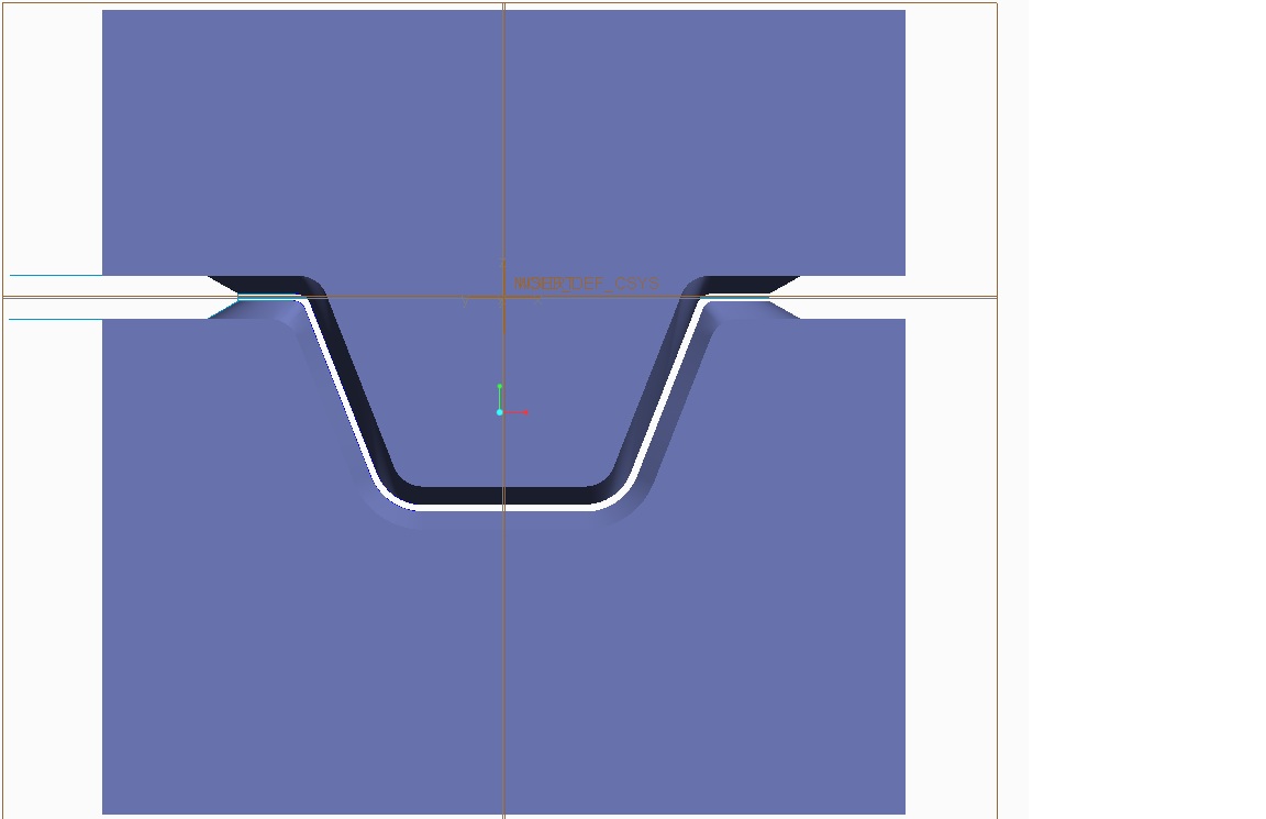
For moldesign of course a zero gap is desirable and only channels and pushers will be added to inject and eject. But based on your picture I assume you are forging sheetmetal (or call it diefacing or bending by forms) and I understand that you therefore want a gap everywhere between the two halves.
Looking at the picture above, I'd say for moldesign functionality:
- The inside area of the gap between the upper and lower part would be normally created by the design part (bend or forged state) that is assembled to the moldesign assembly.
- But yes, the gaps at the outside will require additional features to be added to either half.
You may consider using offset surface functionality to generate a second split surface with constant offset from the first one. Then a simple split with one volume option could be done on the half that needs it.
Oct 01, 2013
04:30 PM
- Mark as New
- Bookmark
- Subscribe
- Mute
- Subscribe to RSS Feed
- Permalink
- Notify Moderator
Please log in to access translation
Oct 01, 2013
04:30 PM
In our job application we seem to have the best  of both worlds. In the job shown there is a flash depth for the entire die. In other jobs we have zero thickness in parting line yet there is thickness in the flash and gutter. I'm not sure how we'll get past these hurdles; there is a considerable ammount of re-learning of technique involved.
I have wondered if some of our die work could be simplified by doing surface offsets or shells in the parting areas.
Oct 07, 2013
06:04 AM
- Mark as New
- Bookmark
- Subscribe
- Mute
- Subscribe to RSS Feed
- Permalink
- Notify Moderator
Please log in to access translation
Oct 07, 2013
06:04 AM
- Shells are used for adding solid geometry, so would be usable with the design model only
- For gaps with constant width, offset surface features should be the fastest way.
- For varying gaps, you will need additional (surface) features.
If you notice repeating patterns within the feature you create while designing your dies, consider the use of UDFs (user-defined features), which allow you to apply one or more pre-defined features by only specifying the new references.
The trick to make UDFs useful, is to find the right balance (normally requiring some experimenting):
- They should save as much time as possible by applying complex and/or multiple features with few clicks
- They should be simple/general enough to allow reuse as often as possible
(There is no use, if creating UDFs takes as much time as will be saved by using them)


