
Turn on suggestions
Auto-suggest helps you quickly narrow down your search results by suggesting possible matches as you type.
Showing results for
Please log in to access translation
Turn on suggestions
Auto-suggest helps you quickly narrow down your search results by suggesting possible matches as you type.
Showing results for
Community Tip - Did you get called away in the middle of writing a post? Don't worry you can find your unfinished post later in the Drafts section of your profile page. X
- Community
- Creo+ and Creo Parametric
- 3D Part & Assembly Design
- Split surface in Creo for analysis in Ansys?
Translate the entire conversation x
Please log in to access translation
Options
- Subscribe to RSS Feed
- Mark Topic as New
- Mark Topic as Read
- Float this Topic for Current User
- Bookmark
- Subscribe
- Mute
- Printer Friendly Page
Split surface in Creo for analysis in Ansys?
Sep 07, 2015
08:11 AM
- Mark as New
- Bookmark
- Subscribe
- Mute
- Subscribe to RSS Feed
- Permalink
- Notify Moderator
Please log in to access translation
Sep 07, 2015
08:11 AM
Split surface in Creo for analysis in Ansys?
I'm a novice in Ansys and I'm trying to split a surface to apply a load on a portion of that surface. How do I do this in Creo?
Solved! Go to Solution.
Labels:
- Labels:
-
Surfacing
ACCEPTED SOLUTION
Accepted Solutions
Dec 16, 2015
05:03 PM
- Mark as New
- Bookmark
- Subscribe
- Mute
- Subscribe to RSS Feed
- Permalink
- Notify Moderator
Please log in to access translation
Dec 16, 2015
05:03 PM
Mat's
I found (by accident) that if I enter Ansys whilst in Simulate then the selectable surfaces equivalent to the surface regions appear in Ansys.
17 REPLIES 17
Sep 07, 2015
08:21 AM
- Mark as New
- Bookmark
- Subscribe
- Mute
- Subscribe to RSS Feed
- Permalink
- Notify Moderator
Please log in to access translation
Sep 07, 2015
08:21 AM
As far as I'm aware, there's no way to do this 'properly' in the main Creo modeller. Presumably if you create a surface region within Mechanica (sorry, Simulate) and then mesh it in Simulate to export to Ansys, that will do what you need.
Otherwise, one suggestion I've heard is to create a very small step in the surface to force an edge (you can probably then delete the tiny vertical elements within Ansys and 'merge' the two resulting free edges).
Another technique, depending on the geometry might be convert your model to surfaces and delete either the surface for load attachment, or the surrounding surfaces, and then re-create the missing surface in Ansys (or you could cut/delete surfaces twice and export two sets of surfaces) - but I'm just brainstorming now!
Sep 07, 2015
08:26 AM
- Mark as New
- Bookmark
- Subscribe
- Mute
- Subscribe to RSS Feed
- Permalink
- Notify Moderator
Please log in to access translation
Sep 07, 2015
08:26 AM
I just succeeded with a variant of your last suggestion. I have played around with a lot of alternatives, unfortunately I can't remember the exact steps but it went something like this. Open the model in FEM mode. Being in FEM mode, with your surface regions completed, click "Save as" and choose iges as the file type. This is now imported to ansys with the proper split of surfaces...
Sep 07, 2015
08:28 AM
- Mark as New
- Bookmark
- Subscribe
- Mute
- Subscribe to RSS Feed
- Permalink
- Notify Moderator
Please log in to access translation
Sep 07, 2015
08:28 AM
Nice - that's worth remembering! Export the IGES (or possibly STEP) from a Mechanica session...
Sep 07, 2015
08:42 AM
- Mark as New
- Bookmark
- Subscribe
- Mute
- Subscribe to RSS Feed
- Permalink
- Notify Moderator
Please log in to access translation
Sep 07, 2015
08:42 AM
I actually entered FEM mode. Exporting an iges is only possible for compressed shell models in Creo Simulate. STEP can not be exported from Creo Simulate. If you enter FEM-mode however, it is possible to export step aswell as iges. Fem mode is activated under the "Model setup"-menu.
Sep 07, 2015
09:59 AM
- Mark as New
- Bookmark
- Subscribe
- Mute
- Subscribe to RSS Feed
- Permalink
- Notify Moderator
Please log in to access translation
Sep 07, 2015
09:59 AM
Another suggestion from a colleague:
If you convert the model to surfaces (take a copy of the surface set), you can 'trim' a surface but 'keep both sides'. Then you can export just the surfaces, either by choosing that option or by exporting only a layer with the surfaces on it.
Sep 07, 2015
03:14 PM
- Mark as New
- Bookmark
- Subscribe
- Mute
- Subscribe to RSS Feed
- Permalink
- Notify Moderator
Please log in to access translation
Sep 07, 2015
03:14 PM
Another way is exporting solid model with surfaces patches where you need to load or costraint and use command FACESPLIT in Workbench.
Dec 16, 2015
05:03 PM
- Mark as New
- Bookmark
- Subscribe
- Mute
- Subscribe to RSS Feed
- Permalink
- Notify Moderator
Please log in to access translation
Dec 16, 2015
05:03 PM
Mat's
I found (by accident) that if I enter Ansys whilst in Simulate then the selectable surfaces equivalent to the surface regions appear in Ansys.
Jan 10, 2016
10:17 PM
- Mark as New
- Bookmark
- Subscribe
- Mute
- Subscribe to RSS Feed
- Permalink
- Notify Moderator
Please log in to access translation
Jan 10, 2016
10:17 PM
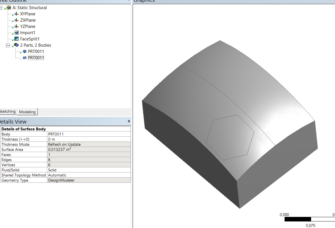
you create a slicing sketch on a plane in designmodeler. usually a large rectangle , create surface from sketch. Freeze both surfaces. Slice using surface. Use the plane you created as the tool. You will now what 3 bodies. Suppress the cutting plane. You will have to bond edges in Structural. I just learned the hard way. Completely different methodology that Creo.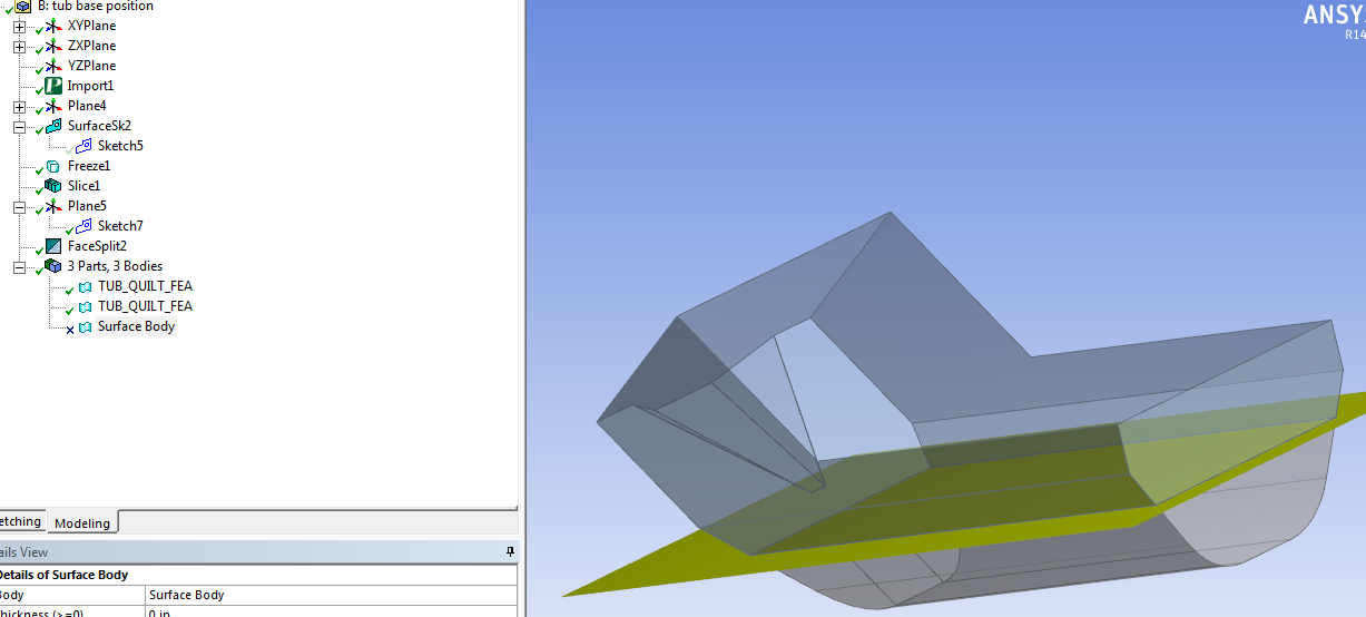
Jan 11, 2016
04:26 AM
- Mark as New
- Bookmark
- Subscribe
- Mute
- Subscribe to RSS Feed
- Permalink
- Notify Moderator
Please log in to access translation
Jan 11, 2016
04:26 AM
That assumes one has a Design Modeller license
Regards
Jan 11, 2016
04:32 AM
- Mark as New
- Bookmark
- Subscribe
- Mute
- Subscribe to RSS Feed
- Permalink
- Notify Moderator
Please log in to access translation
Jan 11, 2016
04:32 AM
Yes. I was hoping I could do this with Creo+ANSYS only. We have access to Spaceclaim, but I don't want yet another software to learn.
Jan 11, 2016
09:49 AM
- Mark as New
- Bookmark
- Subscribe
- Mute
- Subscribe to RSS Feed
- Permalink
- Notify Moderator
Please log in to access translation
Jan 11, 2016
09:49 AM
Ok then. taking my example. Create two parts. Top and bottom in creo. assembly them. bring into ANSYS as surface bodies. bond the edges in structural. be careful when picking target and contact edges.
Jan 11, 2016
03:09 PM
- Mark as New
- Bookmark
- Subscribe
- Mute
- Subscribe to RSS Feed
- Permalink
- Notify Moderator
Please log in to access translation
Jan 11, 2016
03:09 PM
If you have design modeler license, for me simplest way is extrude a sketch with option imprint faces. So this command creates Patches.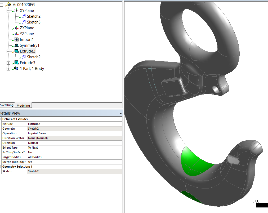
Jan 12, 2016
02:37 AM
- Mark as New
- Bookmark
- Subscribe
- Mute
- Subscribe to RSS Feed
- Permalink
- Notify Moderator
Please log in to access translation
Jan 12, 2016
02:37 AM
Nice! I actually helped a company here in Sweden with some training and modeling techniques for exactly this kind of product! But that was all in Creo Simulate so then this was not an issue.
Jan 12, 2016
08:24 AM
- Mark as New
- Bookmark
- Subscribe
- Mute
- Subscribe to RSS Feed
- Permalink
- Notify Moderator
Please log in to access translation
Jan 12, 2016
08:24 AM
I m new to Ansys and I tried to Imprint a sketch on a curved surface and I couldn't get it to generate. I created my sketch on a plane offset from my csys outside my body like we do in Creo. I thought this was equivalent to project in Creo. Is there a trick or an order to selecting?
Jan 12, 2016
02:04 PM
- Mark as New
- Bookmark
- Subscribe
- Mute
- Subscribe to RSS Feed
- Permalink
- Notify Moderator
Please log in to access translation
Jan 12, 2016
02:04 PM
After creating closed sketch you have to create an extrusion (not adding material, not removing it) with imprinting of faces (Operation). Look carefully at picture i posted.
There I extruded a circle
Jan 13, 2016
12:50 PM
- Mark as New
- Bookmark
- Subscribe
- Mute
- Subscribe to RSS Feed
- Permalink
- Notify Moderator
Please log in to access translation
Jan 13, 2016
12:50 PM
got it to work...Thanks
Apr 28, 2017
04:54 AM
- Mark as New
- Bookmark
- Subscribe
- Mute
- Subscribe to RSS Feed
- Permalink
- Notify Moderator
Please log in to access translation
Apr 28, 2017
04:54 AM
Hi
I just came across the same question and got the following procedure worked (that the customer do not have Ansys-Design Modeler - Direct from Creo).
So this can be another method to solve this.
Basically you need to think in terms of surfaces to split and so have to export as iges format first.
Re-import into Creo back (make sure the options "Solidify" as "off" during import options).
Insert a profile (corresponding to the area that you want to apply inside Ansys force/pressure later) before imported feature. i.e this feature is before the imported feature in the features tree list. Then it can be accessed by imported feature after this. This profile has to be on the surface going to be split later. So can be directly sketched if the surface is flat or projected if surface is not flat.
Select the surface (that is to be split) and trim this using the above profile. Use trim surface feature. Make sure select 3rd option of split that keeps both faces.
Now export as iges file and Ansys should be happy now.
- Singaram Ravi


