
Turn on suggestions
Auto-suggest helps you quickly narrow down your search results by suggesting possible matches as you type.
Showing results for
Please log in to access translation
Turn on suggestions
Auto-suggest helps you quickly narrow down your search results by suggesting possible matches as you type.
Showing results for
Community Tip - Have a PTC product question you need answered fast? Chances are someone has asked it before. Learn about the community search. X
- Community
- Creo+ and Creo Parametric
- 3D Part & Assembly Design
- Summary-screw threads
Translate the entire conversation x
Please log in to access translation
Options
- Subscribe to RSS Feed
- Mark Topic as New
- Mark Topic as Read
- Float this Topic for Current User
- Bookmark
- Subscribe
- Mute
- Printer Friendly Page
Summary-screw threads
Aug 31, 2011
10:56 AM
- Mark as New
- Bookmark
- Subscribe
- Mute
- Subscribe to RSS Feed
- Permalink
- Notify Moderator
Please log in to access translation
Aug 31, 2011
10:56 AM
Summary-screw threads
Thanks to all who responded. All good stuff. I'll probably start off with ending my sweep profile with either an angle or curve as suggested below, but will also try some of the other suggestions, and take a look at the videos from Art.
A thanks also to Joe for offering up some examples (Joe, I'll let you know if I need any).
Stefan
1. Don't add the thread as a protrusion - cut the thread into the major OD.
2. You can create screw threads for standard screws. Or you can go to www.mcmaster.com<">http://www.mcmaster.com> and download any number of formats of standard screws.
Neal
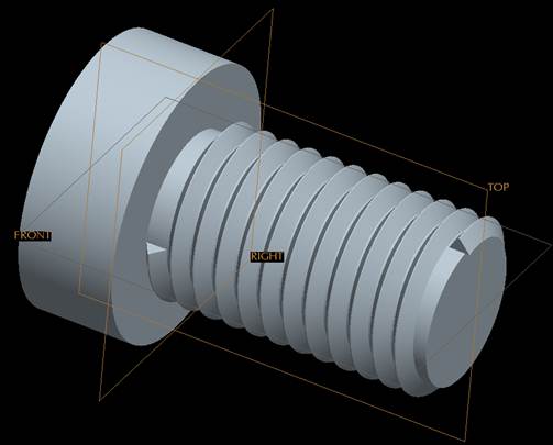
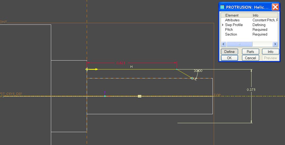
3. It looks like your threads are protruded rather than a cut, correct? Taper your sweep profile into the part. In the thread form sketch, be sure to not be using a centerline & reference the form on that minor dia I see in the part. If you have a centerline, the feature will fail because you can't run the thread out if you have conflicting constraints I could send you examples or even model it for you but I am in WF4.
4. Somebody may have already said but you can change the profile of the sweep trajectory to give the run out at the start of the thread. Instead of a straight line you add a slope at the end or even an arc.
5. Sometimes it helps to do the thread sweep as a surface then construct the end details in surfaces and merge them before solidifying the thread. As others have said you can get standard screws with thread if you look and mostly it is not necessary or even desirable. That said sometimes it is required in which case i have used the methods outlined above with good success.
6. I think a key issue is, it appears you are doing a helical sweep, when what you need
is a helical CUT. Much more likely to get what you want that way.
7. Create the OD, with a chamfer down to whatever the spigot diameter is, then simply cut from the spigot end.
8. A couple of videos that may help?
This thread is inactive and closed by the PTC Community Management Team. If you would like to provide a reply and re-open this thread, please notify the moderator and reference the thread. You may also use "Start a topic" button to ask a new question. Please be sure to include what version of the PTC product you are using so another community member knowledgeable about your version may be able to assist.
A thanks also to Joe for offering up some examples (Joe, I'll let you know if I need any).
Stefan
1. Don't add the thread as a protrusion - cut the thread into the major OD.
2. You can create screw threads for standard screws. Or you can go to www.mcmaster.com<">http://www.mcmaster.com> and download any number of formats of standard screws.
Neal
3. It looks like your threads are protruded rather than a cut, correct? Taper your sweep profile into the part. In the thread form sketch, be sure to not be using a centerline & reference the form on that minor dia I see in the part. If you have a centerline, the feature will fail because you can't run the thread out if you have conflicting constraints I could send you examples or even model it for you but I am in WF4.
4. Somebody may have already said but you can change the profile of the sweep trajectory to give the run out at the start of the thread. Instead of a straight line you add a slope at the end or even an arc.
5. Sometimes it helps to do the thread sweep as a surface then construct the end details in surfaces and merge them before solidifying the thread. As others have said you can get standard screws with thread if you look and mostly it is not necessary or even desirable. That said sometimes it is required in which case i have used the methods outlined above with good success.
6. I think a key issue is, it appears you are doing a helical sweep, when what you need
is a helical CUT. Much more likely to get what you want that way.
7. Create the OD, with a chamfer down to whatever the spigot diameter is, then simply cut from the spigot end.
8. A couple of videos that may help?
This thread is inactive and closed by the PTC Community Management Team. If you would like to provide a reply and re-open this thread, please notify the moderator and reference the thread. You may also use "Start a topic" button to ask a new question. Please be sure to include what version of the PTC product you are using so another community member knowledgeable about your version may be able to assist.
Labels:
- Labels:
-
General
9 REPLIES 9
Aug 31, 2011
11:18 AM
- Mark as New
- Bookmark
- Subscribe
- Mute
- Subscribe to RSS Feed
- Permalink
- Notify Moderator
Please log in to access translation
Aug 31, 2011
11:18 AM
Although threads are interesting features to model, be careful about
adding them to your models by default.
Like modeling knurling and springs, they are resource hogs and will
bring the CAD system performance down greatly.
They are not typically used by NC machining.
Except for specific cases actual screw threads are not used for FEA
analysis, etc...
Other CAD systems render the threads using texture maps for shading,
etc...
Just my $.02,
Christopher F. Gosnell
FPD Company
124 Hidden Valley Road
McMurray, PA 15317
Aug 31, 2011
11:32 AM
- Mark as New
- Bookmark
- Subscribe
- Mute
- Subscribe to RSS Feed
- Permalink
- Notify Moderator
Please log in to access translation
Aug 31, 2011
11:32 AM
Yep, every time I download a McMaster screw, I add a feature to fill in
the threads because the bog down the system so much.
Doug Schaefer
the threads because the bog down the system so much.
Doug Schaefer
Aug 31, 2011
11:56 AM
- Mark as New
- Bookmark
- Subscribe
- Mute
- Subscribe to RSS Feed
- Permalink
- Notify Moderator
Please log in to access translation
Aug 31, 2011
11:56 AM
Someone sent me this part as a test. But, Does anyone know the best approach of how to model this part.This requires someone who is an expert on surfacing I think. Can someone model this and let me know how they did it. I would really like to know how to model this Epart in proe
Thanks,
Evan
Thanks,
Evan
Aug 31, 2011
12:24 PM
- Mark as New
- Bookmark
- Subscribe
- Mute
- Subscribe to RSS Feed
- Permalink
- Notify Moderator
Please log in to access translation
Aug 31, 2011
12:24 PM
I agree with Chris and the others who have also chimed in. Modeling threads is normally something we don't do. This is a custom part and the threads were requested.
On a side note, we have some SolidWorks users at some of our other sites, and many of the parts I've seen from them, screws, tapped holes, etc, show threads. It was always my understanding that they were driven by a bitmap file, or something like that (Chris mentiones texture mapss below) but that they weren't actually modeled. I wonder if they impact memory/performance.
Stefan
Aug 31, 2011
12:35 PM
- Mark as New
- Bookmark
- Subscribe
- Mute
- Subscribe to RSS Feed
- Permalink
- Notify Moderator
Please log in to access translation
Aug 31, 2011
12:35 PM
Our company had a project some years ago (modelled by a bunch of
contractors, in the main part) in which every Spirol pin had 2.25 turns
and bevelled ends; every electrical connector had the manufacturer's
logo in raised lettering; some bolts may even have shown the grade on
the head - although I think they drew the line at threads!
When the assembly was finished, it couldn't be opened in Master Rep on a
32bit machine. At that time, I don't think we /had/ any 64bit Windows
machines (although there may have been some Unix systems which could
cope with it).
This was /not/ an example of good modelling practice!
Jonathan
Aug 31, 2011
12:40 PM
- Mark as New
- Bookmark
- Subscribe
- Mute
- Subscribe to RSS Feed
- Permalink
- Notify Moderator
Please log in to access translation
Aug 31, 2011
12:40 PM
Which begs the question: where do threads bog the system down - in the
creation of the threads or the display? I always thought that Doug's
approach, having the threads regenerate, and then the next feature fill them
in or cut them off, would still bog the system down, because it is still
creating & regenerating the threads, even if they get covered up. If the
performance hit is in the math of trying to figure out whether those helical
surfaces need to be displayed or not, then Doug's approach makes sense (as
opposed to my approach, which was to redefine the base import feature &
delete the thread surfaces entirely, and then add a revolved surface to
represent them).
--
Lyle Beidler
MGS Inc
178 Muddy Creek Church Rd
Denver PA 17517
717-336-7528
Fax 717-336-0514
<">mailto:-> -
<">http://www.mgsincorporated.com>
Aug 31, 2011
01:07 PM
- Mark as New
- Bookmark
- Subscribe
- Mute
- Subscribe to RSS Feed
- Permalink
- Notify Moderator
Please log in to access translation
Aug 31, 2011
01:07 PM
I believe it's the display/rendering. I too have used Carr-lane and
McMaster-Carr parts that have 'real' threads and knurling bog the system
down, until I de-featured the models by covering over the threads,
etc... For some reason though, my downloaded (dumb solid) Smalley wave
springs seem to cause assemblies to display slower than my own created
springs(helical sweep with trajpar wave).
I would hope that most CAD systems would resort to bump maps or texture
maps to 'show' features like knurls, threads, etc...
Christopher F. Gosnell
FPD Company
124 Hidden Valley Road
McMurray, PA 15317
Sep 02, 2011
09:09 AM
- Mark as New
- Bookmark
- Subscribe
- Mute
- Subscribe to RSS Feed
- Permalink
- Notify Moderator
Please log in to access translation
Sep 02, 2011
09:09 AM
That works for me. But try explaining to the PHB's (point hair bosses)
why your fancy CAD system doesn't show threads during a presentation or
design review.
Christopher F. Gosnell
FPD Company
124 Hidden Valley Road
McMurray, PA 15317
why your fancy CAD system doesn't show threads during a presentation or
design review.
Christopher F. Gosnell
FPD Company
124 Hidden Valley Road
McMurray, PA 15317
Sep 02, 2011
09:27 AM
- Mark as New
- Bookmark
- Subscribe
- Mute
- Subscribe to RSS Feed
- Permalink
- Notify Moderator
Please log in to access translation
Sep 02, 2011
09:27 AM
On the other hand try conducting an engineering review with sections in GA and detail drawings showing a black mess of zig-zags rather than the conventional representations given by using cosmetic thread features.
Although rather a kluge, the SolidWorks thread graphic image displayed in model views for cosmetic threads works, IMO, quite well in practice.
John Prentice
Although rather a kluge, the SolidWorks thread graphic image displayed in model views for cosmetic threads works, IMO, quite well in practice.
John Prentice


