Community Tip - You can change your system assigned username to something more personal in your community settings. X
- Community
- Creo+ and Creo Parametric
- 3D Part & Assembly Design
- Re: Table Pattern in assembly with Part dimensiona...
- Subscribe to RSS Feed
- Mark Topic as New
- Mark Topic as Read
- Float this Topic for Current User
- Bookmark
- Subscribe
- Mute
- Printer Friendly Page
Table Pattern in assembly with Part dimensional control
- Mark as New
- Bookmark
- Subscribe
- Mute
- Subscribe to RSS Feed
- Permalink
- Notify Moderator
Table Pattern in assembly with Part dimensional control
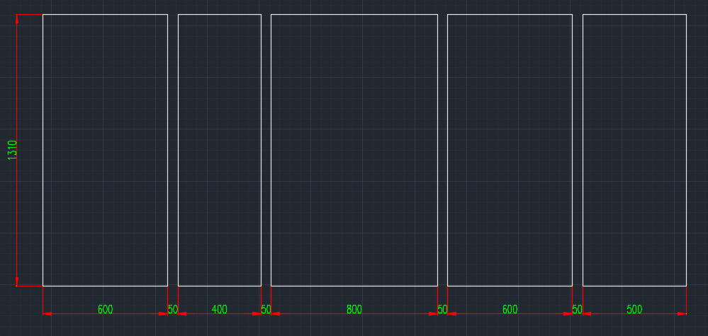
I want to pattern a glass. It is a subassembly (Double glass with air spacer and silicone) which is controlled by a Skelton and assembly parameters. The width of the glass keeps changing and accordingly the pattern X-Dir value. Hope the below image explains it.

Please give me an idea to do this.
Regards
Basil
This thread is inactive and closed by the PTC Community Management Team. If you would like to provide a reply and re-open this thread, please notify the moderator and reference the thread. You may also use "Start a topic" button to ask a new question. Please be sure to include what version of the PTC product you are using so another community member knowledgeable about your version may be able to assist.
- Labels:
-
Assembly Design
- Mark as New
- Bookmark
- Subscribe
- Mute
- Subscribe to RSS Feed
- Permalink
- Notify Moderator
Hi, I would make a model of a glass part as a generic. In tools\ family table\ you can add instances that will allow you to control anything that you like. From the screen shot add the width dimension. Then you need to do the same thing in the assembly. Make a generic one and add the glass to it and any other changing components like silicone spacer (it too will need to be modeled in a family table so you can drive the matching sizes (silicone-600, silicone-500, etc)
So now you should have a series of double glazed panels ready for the main assembly.
In the skeleton I would be tempted to assemble each unit to a co-ordinate system, say on the bottom left. The co-ordinate system then can be patterned and each version of glass located individually as units. Use pattern table to drive the locations at 0, 650, 1100, 1950 etc
you may want to add parameters to the tables such as description etc that vary with the parts and assemblies if you want to report these in tables for bom's
Job done.
- Mark as New
- Bookmark
- Subscribe
- Mute
- Subscribe to RSS Feed
- Permalink
- Notify Moderator
The number of glasses varies from 1-30 depending on the situation. The width can vary from 125 to 3000mm for each glass. (Glass can be absent in some instance too). We cannot create a set of glass sizes, as the variation in size can be as low as 0.5mm.
So each time, when we regenerate the assembly for new scenario, do we need to edit the family table and the pattern table? Is there any way we can update the assembly parameters and then these tables get updated automatically?
Thanks in advance.
- Mark as New
- Bookmark
- Subscribe
- Mute
- Subscribe to RSS Feed
- Permalink
- Notify Moderator
Hi,
your sub-assembly contains 1-30 parts (glasses), so you can:
- create 30 parts ... glass_01.prt, glass_02.prt, ... glass_30.prt
- in every part you can set user name for width dimension ... eg. glass_01_width
- assemble all 30 parts into "glass" sub-assembly
- define assembly relations
glass_01_width:ID=default value
glass_02_width:ID=default value
... and so on
When you need to generate specific glass configuration, then:
- open "glass" sub-assembly
- modify width values through relations
- regenerate
- suppress unwanted "glass" parts
MH
Martin Hanák
- Mark as New
- Bookmark
- Subscribe
- Mute
- Subscribe to RSS Feed
- Permalink
- Notify Moderator
Flexible components?
- Mark as New
- Bookmark
- Subscribe
- Mute
- Subscribe to RSS Feed
- Permalink
- Notify Moderator
If you want to build an assembly of panels, then I think you have to commit to having one assembly family table. In the example below, the generic panel assembly is comprised of 3 flexible components: 2x glass pane and 1x gasket / frame (the glass panes and frame adapt in size based on assembly-level sketch or distances between assembly datums, etc...)
A family table of "available panels" was prepared.
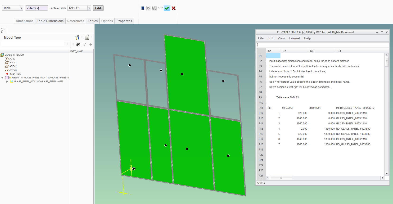
At last, the final assembly was started and an instance of the assembled panel is placed in it. This is then be arranged into a grid with a table-pattern:

Yes, you will have to edit both the family table and the pattern table if you make new design...
But keep in mind that you can edit the family table using excel. This makes it fairly simple to generate the inventory of all possible glass sizes.
Also, there are similar ways of editing the pattern table instead of using the clunky Pro/Table (you can read and write .ptb files by right-clicking in the "Tables" tab).
- Mark as New
- Bookmark
- Subscribe
- Mute
- Subscribe to RSS Feed
- Permalink
- Notify Moderator
I have not used skeletons much, but I believe a skeleton and simplified reps may get what you need. The skeleton would simply be lines to control height, width, and of individual panes and maybe CSYS for location. The simplified rep would control how many panes are shown. You would need 30 pane models and 30 silicone models.
There is always more to learn in Creo.
- Mark as New
- Bookmark
- Subscribe
- Mute
- Subscribe to RSS Feed
- Permalink
- Notify Moderator


