Turn on suggestions
Auto-suggest helps you quickly narrow down your search results by suggesting possible matches as you type.
Showing results for
Please log in to access translation
Turn on suggestions
Auto-suggest helps you quickly narrow down your search results by suggesting possible matches as you type.
Showing results for
Community Tip - Did you get called away in the middle of writing a post? Don't worry you can find your unfinished post later in the Drafts section of your profile page. X
- Community
- Creo+ and Creo Parametric
- 3D Part & Assembly Design
- Trying to learn Spine Bend
Translate the entire conversation x
Please log in to access translation
Options
- Subscribe to RSS Feed
- Mark Topic as New
- Mark Topic as Read
- Float this Topic for Current User
- Bookmark
- Subscribe
- Mute
- Printer Friendly Page
Trying to learn Spine Bend
Aug 14, 2012
08:50 AM
- Mark as New
- Bookmark
- Subscribe
- Mute
- Subscribe to RSS Feed
- Permalink
- Notify Moderator
Please log in to access translation
Aug 14, 2012
08:50 AM
Trying to learn Spine Bend
I'm certain that I can modify 2 straight developed cylinders into Spine Bend Features. I unfortunately don't understand the specific steps needed to build this.
Could someone help me with the details of how this would be done?
I believe I've seen a thread suggest that you would need a start and end datum. When the term datum is used do they by chance mean start and end curves?
I always error out when I try to follow the Spine Bend routine.
I will attach a picture of the model I am hoping to have bent.
This thread is inactive and closed by the PTC Community Management Team. If you would like to provide a reply and re-open this thread, please notify the moderator and reference the thread. You may also use "Start a topic" button to ask a new question. Please be sure to include what version of the PTC product you are using so another community member knowledgeable about your version may be able to assist.
Labels:
- Labels:
-
General
14 REPLIES 14
Aug 14, 2012
01:15 PM
- Mark as New
- Bookmark
- Subscribe
- Mute
- Subscribe to RSS Feed
- Permalink
- Notify Moderator
Please log in to access translation
Aug 14, 2012
01:15 PM
Aug 14, 2012
09:23 PM
- Mark as New
- Bookmark
- Subscribe
- Mute
- Subscribe to RSS Feed
- Permalink
- Notify Moderator
Please log in to access translation
Aug 14, 2012
09:23 PM
I appreciate the attached video but I can't follow this through to the solution for my own application.
I don't understand how this function sets up in what you can and can not do. It appears that you can do very different types of applications but the key entries needed are quite confusing.
Aug 14, 2012
09:29 PM
- Mark as New
- Bookmark
- Subscribe
- Mute
- Subscribe to RSS Feed
- Permalink
- Notify Moderator
Please log in to access translation
Aug 14, 2012
09:29 PM
Hi guys...
I can help with this. Spinal bend can create some cool geometry but it's not so well known for being accurate. It can actually stretch or compress geometry in unexpected ways. I will be happy to demonstrate this feature if you'd like. I can either do some powerpoint slides or we can just do a quick GoToMeeting.
The basics of a spinal bend are the curve itself (the "spine") and then two parallel planes or surfaces that define the area you wish to bend. You can bend an entire object or just portion. Let me know how you'd like me to explain this... I'm happy to use either method.
Thanks!
-Brian
Aug 14, 2012
09:45 PM
- Mark as New
- Bookmark
- Subscribe
- Mute
- Subscribe to RSS Feed
- Permalink
- Notify Moderator
Please log in to access translation
Aug 14, 2012
09:45 PM
I did some playing with it this afternoon and found the one tip in the video to be key to making it work. That is the part about choosing the "defined area". Turned out to be pretty simple once I got past that.
I don't know that I would attempt it as a "tube bender" however.
Aug 15, 2012
12:26 PM
- Mark as New
- Bookmark
- Subscribe
- Mute
- Subscribe to RSS Feed
- Permalink
- Notify Moderator
Please log in to access translation
Aug 15, 2012
12:26 PM
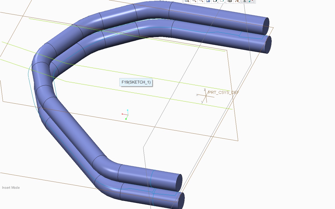
It's a powerful command, but a little tricky until you get used to it. The plane "defining volume to bend" means just that. For instance, if you have a tube with holes in it that's 10" long, and your 2 planes are 5" apart, that 5" will be stretched the length of that spine, however long that is. Conversely, if your planes are 20" apart, it will compact that volume along the spine length. So, to eliminate or minimize any distortion, make sure the planes are where you want them, and that your spine is the correct length (in this case, 10" total).
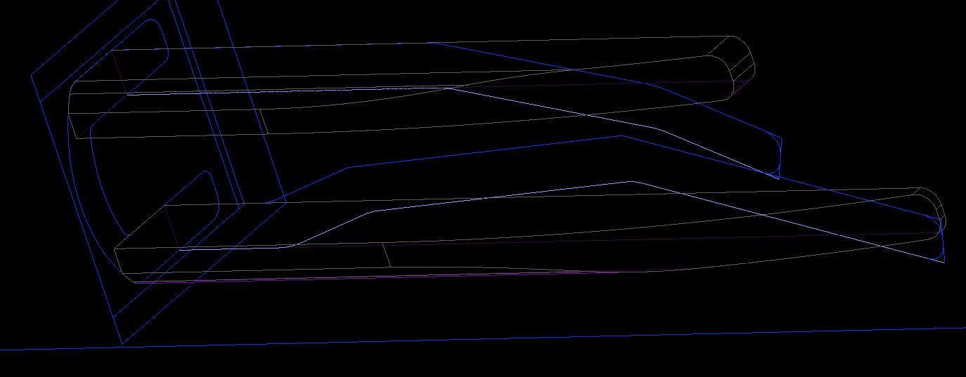
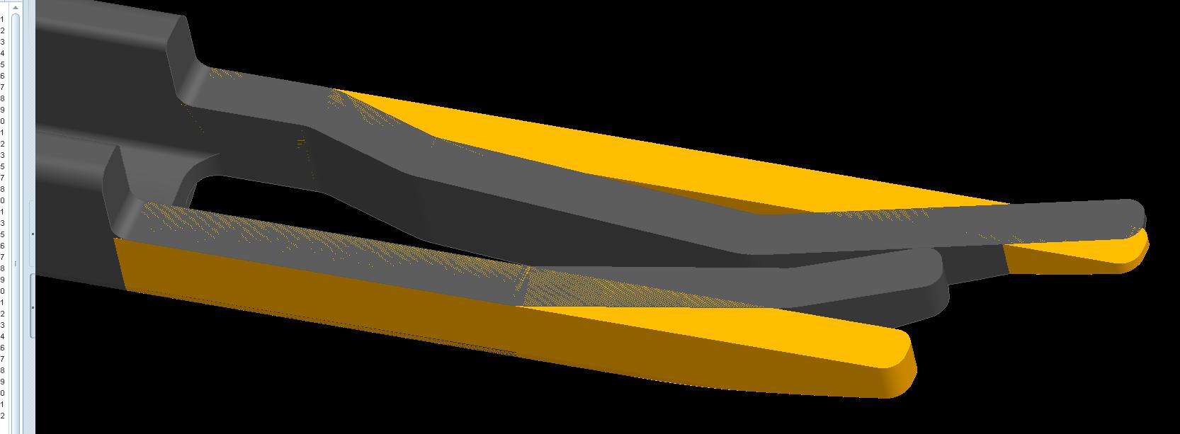
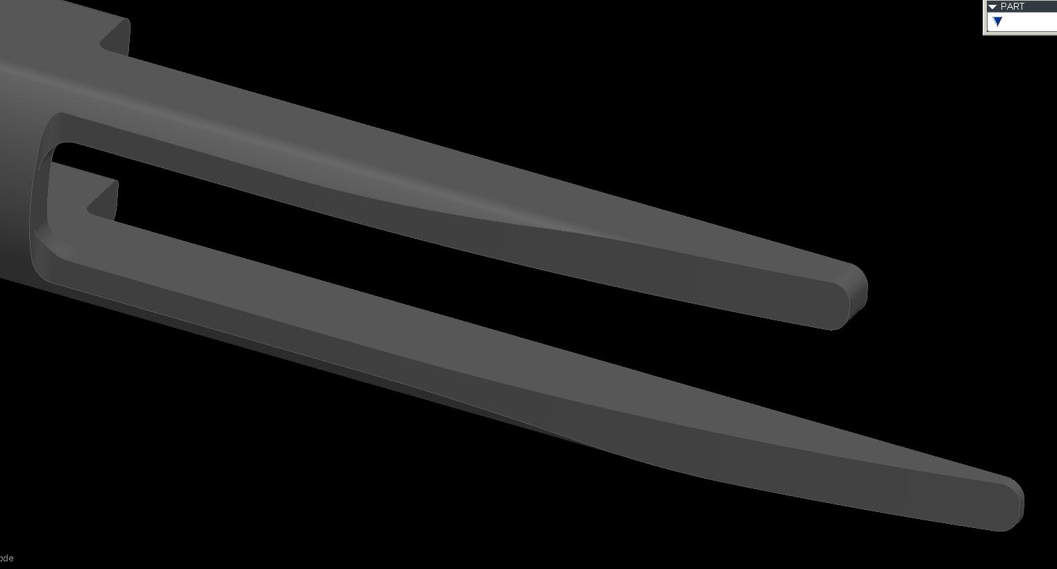
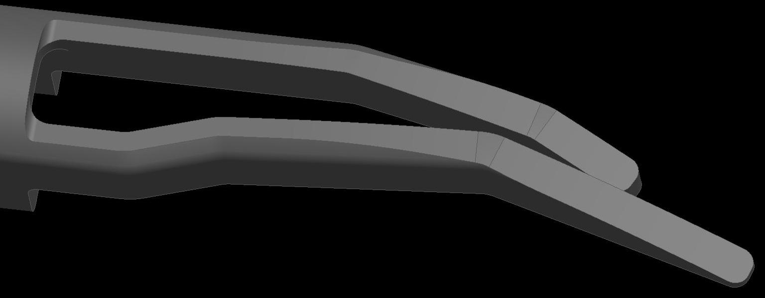
So, for the parts you see below, I made a sketch of the geometry I wanted. I knew that the legs would be made from an extruded shape, and then have a radial cut normal to the extrusion's centerline. Then, the legs would get bent, but I wanted to have the inside length of the bend remain the same and stretch the outer length. So, I created a datum curve of the geometry for both legs I wanted. Copied the inside curve segments I wanted to use as a spine separately for both legs as it's own curve. I then used an evaluate feature and a relation to drive the surfaces I extruded and merged with the radial cut. I did surfaces because I had 2 spinal bends to make, and it allows greater flexibility as when I'm all done with the spinal bends I can solidify them whereas if you're trying to bend a solid, you get EVERYTHING in that "volume to bend". Then I used 2 spinal bends to get the final geometry. I did this becase I have a family table with instances of this part in the raw, extruded length, with the straight legs length (for the vendor), and with the final bent length. It seems to have worked out very well as the vendor is really happy I can tell him the length of the legs to start with, and as you can see the geometry is correct for the cuts (normal to the sides not normal to the extruded centerline).
Good luck!
Oct 23, 2012
11:41 AM
- Mark as New
- Bookmark
- Subscribe
- Mute
- Subscribe to RSS Feed
- Permalink
- Notify Moderator
Please log in to access translation
Oct 23, 2012
11:41 AM
Hi Frank,
I'm sorry I'm very slow to get back to discuss your suggestion. Our company had a couple hot jobs that needed completed and we have been scrambling ever since. We had to complete these jobs in the CAD software which will be replaced for sake of time. Now that more time is freeing up I wanted to trace back.
This method appears to work very well I appreciate this suggestion. You appear to be the master of Spine Bends.
I would like to try applying this in my own application. I'll let you know how this turns out. It's quite possible that nothing will work.
Thank you for your help.
Oct 23, 2012
03:02 PM
- Mark as New
- Bookmark
- Subscribe
- Mute
- Subscribe to RSS Feed
- Permalink
- Notify Moderator
Please log in to access translation
Oct 23, 2012
03:02 PM
I'm almost thinking that there is no possible Spine Bend solution for this application.
What this really needs to bend about is a sketch about the center datum. This means that the spine would not lie along the sweep that needs bent upwards.
In all the examples that I've seen the spine lies along the part that needs bent.
Oct 25, 2012
09:34 AM
- Mark as New
- Bookmark
- Subscribe
- Mute
- Subscribe to RSS Feed
- Permalink
- Notify Moderator
Please log in to access translation
Oct 25, 2012
09:34 AM
I don't want to mislead anyone about my previous answer. You can spine bend a model that the bend spine is not lying on the part geometry. The result unfortunately is too distorted to be usable. In certain applications this could be great.
I can not believe how fussy the entry order is for this feature. There are some prompts sprinkled in for good measure but it is so vague. Without a detailed description of the command how can anyone figure this out?
I happened on an example of using a spine bend in which the spine is not on the part itself. http://www.youtube.com/watch?v=NVwUBKqK9D4 I had to follow the exact keystroke order to get any kind of result.
Aug 24, 2012
10:50 AM
- Mark as New
- Bookmark
- Subscribe
- Mute
- Subscribe to RSS Feed
- Permalink
- Notify Moderator
Please log in to access translation
Aug 24, 2012
10:50 AM
Wow! A lot of views, but no comments?
Aug 24, 2012
11:15 AM
- Mark as New
- Bookmark
- Subscribe
- Mute
- Subscribe to RSS Feed
- Permalink
- Notify Moderator
Please log in to access translation
Aug 24, 2012
11:15 AM
We are just in awe, Frank  It's a perfect application for this type of command.
Aug 24, 2012
11:34 AM
- Mark as New
- Bookmark
- Subscribe
- Mute
- Subscribe to RSS Feed
- Permalink
- Notify Moderator
Please log in to access translation
Aug 24, 2012
11:34 AM
:Yawn:
 Just kidding Frank.
The reason there are no comments is that you've just presented an advanced technique of an already advanced feature. Most people get lost in Spinal Bend at the "define volume to bend" prompt. Those who do understand how to use the basic feature then must learn how to control it. To minimize or at least control compression and elongation, designers must apply measurements, evaluation datums, analysis features, or relations which requires another level of technical skill.
Then you took it over the top by performing multiple spinal bends on surfaces. You did this because otherwise you could not bend those legs separately. If you tried this as a solid, both legs would bend identically. Due to the way you select the bend volume, there would be no way to prevent it. Using surfaces to achieve the desired effect is a stroke of genius.
Finally, you solidified the surfaces and used a family table to create the raw, extruded, and bent instances.
You've used all sorts of tricks to make this part... and each trick requires its own bit of specialized knowledge. It's hard to top this... but for less experienced users it's even harder to understand exactly what you just did. The only thing I could add is that maybe you could use a surface replace rather than a solidify to create the bent legs. This might work better- or it might not work given your need for the family table. I'd probably give it a shot and see if there were any benefits over the Solidify command. Obviously you'll pick whatever works best in your situation.
Although this is a deceptively simple object, there are a whole range of complex techniques used to create it. Certainly this is no less than true old school Pro/ENGINEER (not Creo) artistry. We need to teach people how to make models like this. I think maybe you haven't seen many comments because it's hard to appreciate the intricacies and skill level needed to create such a thing.
I think it's a very impressive model... but then again I understand how you did it! You really should teach a master class in this stuff.
Take care...
-Brian
Aug 24, 2012
01:01 PM
- Mark as New
- Bookmark
- Subscribe
- Mute
- Subscribe to RSS Feed
- Permalink
- Notify Moderator
Please log in to access translation
Aug 24, 2012
01:01 PM
Awwww shucks Brian, you flatter me bro! I just hadn't had a chance to use one in a real world application, and felt this was perfect for it. I just thought that some people might comment or ask how this might work for them, not to stroke my ego. I had fun doing it, learned a few things. Hopefully it'll help some people that might have a similar need. And, I admit at first I didn't understand the "define volume to bend" and so hope I helped describe it so people can better understand it. Sadly I don't feel comfortable posting the model itself as it's a new project. I only felt comfortable posting what I did because you can't see the rest of it.
Oct 23, 2012
10:58 PM
- Mark as New
- Bookmark
- Subscribe
- Mute
- Subscribe to RSS Feed
- Permalink
- Notify Moderator
Please log in to access translation
Oct 23, 2012
10:58 PM
Hi Frank,
firstly I appreciate you for sharing your knowledge. second I would like to say for my enter lever, just like Brian commet, your shown skill is too deep for me, I have seen PTC online traing (https://precisionlms.ptc.com/app/pages/Login) has a brief introduce the skill without detail explanation why and how to setting.
I really need to time to understand advenced skill like this, it is fortuantely up to now I do not met so hard model in my job, otherwise I will spend every my brain cell to find solutiona and post question here.
learning is good things, thank you.
Best regards, Hongjie
Jan 15, 2013
07:15 PM
- Mark as New
- Bookmark
- Subscribe
- Mute
- Subscribe to RSS Feed
- Permalink
- Notify Moderator
Please log in to access translation
Jan 15, 2013
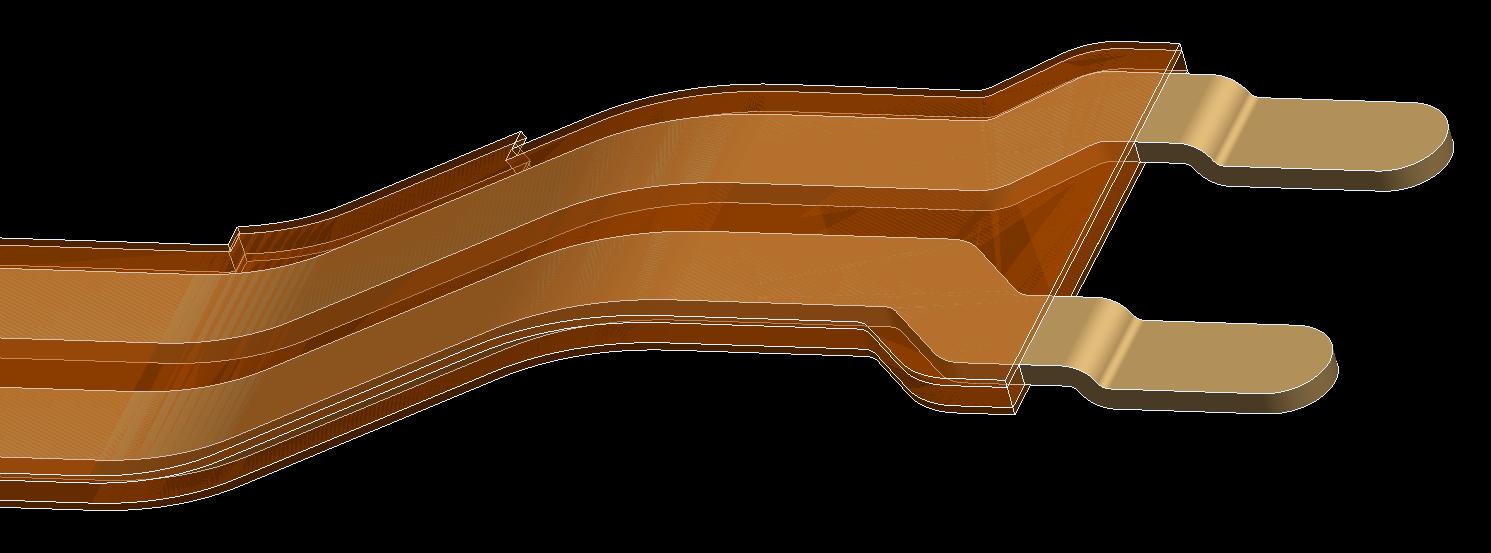
07:15 PM
More spinal bend fun. This time, I had a flex circuit assembly that needed to be in 3 different states: Flat, with just the leads bent (for soldering), and with the leads bent and bent in the final shape. It needed to be an assembly so that I could get different cross-sections for the different layers. So, I had to do 9 family table instances for the basic parts, then 3 different instances at the assembly level to get it all to work. Too bad you can't do a spinal bend on an assembly at the assembly level.