Community Tip - Visit the PTCooler (the community lounge) to get to know your fellow community members and check out some of Dale's Friday Humor posts! X
- Community
- Creo+ and Creo Parametric
- 3D Part & Assembly Design
- Re: Twisted wire not being displayed properly in d...
- Subscribe to RSS Feed
- Mark Topic as New
- Mark Topic as Read
- Float this Topic for Current User
- Bookmark
- Subscribe
- Mute
- Printer Friendly Page
Twisted wire not being displayed properly in drawing
- Mark as New
- Bookmark
- Subscribe
- Mute
- Subscribe to RSS Feed
- Permalink
- Notify Moderator
Twisted wire not being displayed properly in drawing
Hi all
I'm currently having an issue with drawings of assemblies that contain twisted wires (which I'll be making a lot of)
The wires display perfectly fine with a Shaded display, but when I change the display style to "No hidden", I get a lot of extra messy lines that should not be visible. The tangent edges setting and all other "View Display" settings do not have any impact on this. I can't seem to get a clean line drawing of these twists! I know that rendering issues like this happen with interfering parts in assemblies, but the wires are separate and there is no interference.
A picture is attached of the same wires in "Shading" mode and "No hidden" mode.
Any ideas on how to remedy this? Or am I doomed?
Thanks!
This thread is inactive and closed by the PTC Community Management Team. If you would like to provide a reply and re-open this thread, please notify the moderator and reference the thread. You may also use "Start a topic" button to ask a new question. Please be sure to include what version of the PTC product you are using so another community member knowledgeable about your version may be able to assist.
Solved! Go to Solution.
Accepted Solutions
- Mark as New
- Bookmark
- Subscribe
- Mute
- Subscribe to RSS Feed
- Permalink
- Notify Moderator
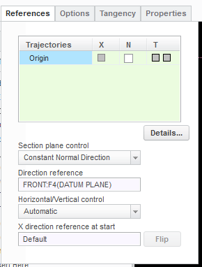
I solved it this way. I went and redefined the first of the twisted wires and changed Section plane control to constant normal direction and chose the FRONT datum plane as my direction. It appears as though it is the end point of the circle that was flowing around causing the little tangent line to display on the drawing. but there is still some issue with the hidden lines not all displaying properly.


- Mark as New
- Bookmark
- Subscribe
- Mute
- Subscribe to RSS Feed
- Permalink
- Notify Moderator
Hi, it is possible to share your part (we can try to investigate your data)
(do not forget add the information about ProE / Creo version - datacode)
Regards,
Vladimir Palffy
- Mark as New
- Bookmark
- Subscribe
- Mute
- Subscribe to RSS Feed
- Permalink
- Notify Moderator
Hi Vladimir
I've attached the .prt file along with a .drw of the two views in my previous screenshot
PTC Creo
Release: 3.0
Date Code: M010
Thank you so much for looking into it! Let me know if I can provide anything else.
- Mark as New
- Bookmark
- Subscribe
- Mute
- Subscribe to RSS Feed
- Permalink
- Notify Moderator
I solved it this way. I went and redefined the first of the twisted wires and changed Section plane control to constant normal direction and chose the FRONT datum plane as my direction. It appears as though it is the end point of the circle that was flowing around causing the little tangent line to display on the drawing. but there is still some issue with the hidden lines not all displaying properly.


- Mark as New
- Bookmark
- Subscribe
- Mute
- Subscribe to RSS Feed
- Permalink
- Notify Moderator
Its likely do to interference. Creo has a hard time drawing lines when geometry overlaps. When you think about it the Math is very complicated.
- Mark as New
- Bookmark
- Subscribe
- Mute
- Subscribe to RSS Feed
- Permalink
- Notify Moderator
Thanks for the reply. There is no interference though. I have seen the problem with overlapping geometry before, but I've checked this model over many times. It's two separate sweeps, twisting around each other, but at no point do they intersect anywhere in the model. The math is still very complicated in this situation, so it's probably a similar issue, but no interference happening.
- Mark as New
- Bookmark
- Subscribe
- Mute
- Subscribe to RSS Feed
- Permalink
- Notify Moderator
It looks like it may be an accuracy situation. I took your model and changed the accuracy as shown to .00005 and then went to the drawing and it made half of the unwanted lines disappear. But if I tried to make it an even smaller accuracy then it wouldn't regenerate it at all. Hope this helps with some more information.
Shane V.
- Mark as New
- Bookmark
- Subscribe
- Mute
- Subscribe to RSS Feed
- Permalink
- Notify Moderator
Maybe try setting accuracy to absolute and setting a value of .0005 inches (or .01016mm)? It's worth a shot.
- Mark as New
- Bookmark
- Subscribe
- Mute
- Subscribe to RSS Feed
- Permalink
- Notify Moderator
Whatever it is, Creo 3.0 M050 apparently fixes it. When I open the drawing I can see the extra edges, but as soon as I make any changes the extra lines go away, and I can't make them reappear.


