Community Tip - Visit the PTCooler (the community lounge) to get to know your fellow community members and check out some of Dale's Friday Humor posts! X
- Community
- Creo+ and Creo Parametric
- 3D Part & Assembly Design
- User need help with Simulation setup.
- Subscribe to RSS Feed
- Mark Topic as New
- Mark Topic as Read
- Float this Topic for Current User
- Bookmark
- Subscribe
- Mute
- Printer Friendly Page
User need help with Simulation setup.
- Mark as New
- Bookmark
- Subscribe
- Mute
- Subscribe to RSS Feed
- Permalink
- Notify Moderator
User need help with Simulation setup.
Hi all,
I have a problem with simulation setup.
To start, I am using creo/elments Pro.
The application: Glass as it fits within seal.
For 3 days now I have tried to get the results of the deflection of the seal as the glass contacts and deforms the seal. The seal interfaces with the glass on 2 sides. I have tried as many combinations of constraints and contact interfaces and have inaccurate results.
Materials.
The tempered glass young's modulus is higher than the polypropylene part. Hence the polypropylene should deform with some degree of prediction. The values can be found in the Creo part file.
The polypropylene young's modulus is based on the flex modulus. Values found in Creo part file.
Simulation requirements.
Parts with fixed positions.
1) Aluminum Channel (first part in model tree)
2) Polypropylene seal (second part in model tree) Note this part should deflect as part 3 (glass) passes by the seal. There are 2 area I am investigating. The polypropylene part has an hour glass or a pinch in area that should deform. This is my problem, how to set up simluation to get deflection of polypropylene).
3) Glass (third part in model tree) Note the glass travels inside of the channel cavity. The glass travels in the negative "X" axis a distance (-30mm). "Y" and "Z" axis are constrainted as fix.
Picture below of assembly with one setup shown. (Sorry, the picture is small, see the attached file call "image 1.png")
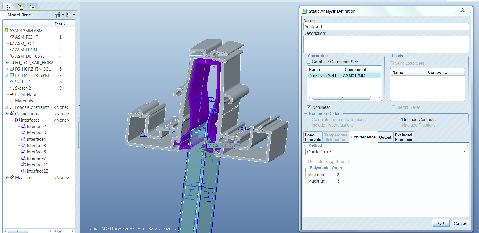
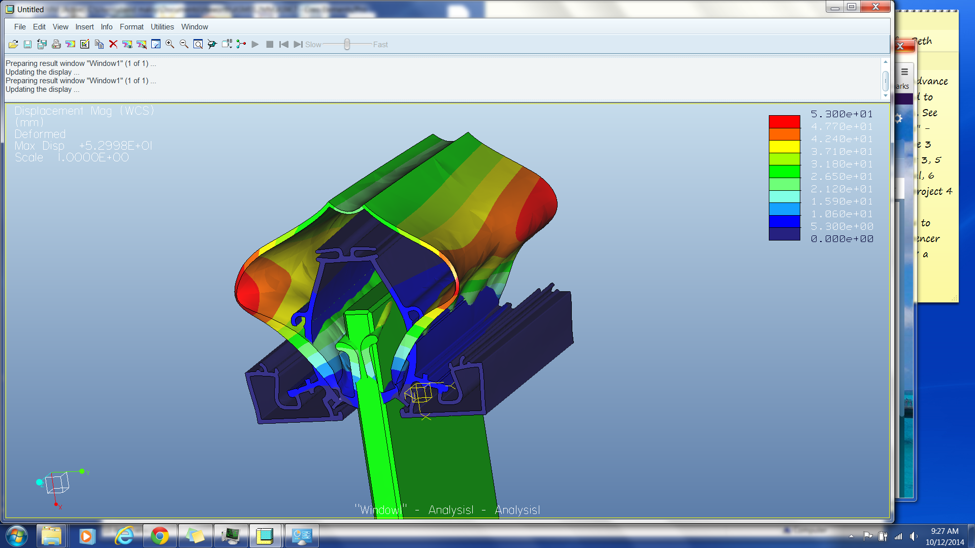
Pictures of some results. See attached file called "results image 1.png"
Cad files available for those that can help me with this problem. (see the zip file called "asm012mm-maloy.asm.zip"
Thanks in advance for the help. I am a one man business and delay has cost me customer relation issues. And I called PTC support and even sent them same files but the technician was unable to help - I think is new to engineering by some of the questions that was asked.
Regards to all.
Dave
This thread is inactive and closed by the PTC Community Management Team. If you would like to provide a reply and re-open this thread, please notify the moderator and reference the thread. You may also use "Start a topic" button to ask a new question. Please be sure to include what version of the PTC product you are using so another community member knowledgeable about your version may be able to assist.
Solved! Go to Solution.
- Labels:
-
Assembly Design
Accepted Solutions
- Mark as New
- Bookmark
- Subscribe
- Mute
- Subscribe to RSS Feed
- Permalink
- Notify Moderator
David,
A quick look and the following comments ...
- Model is symmetric, cut it in half. This will reduce the number of contacts and provide a model that is easier to constrain.
- You have tried to constrain the ends of the rubber by fully fixing rotations. This will have no effect on this solid model (rotational constraints will have an effect for shells/beams).Your model is solid, don't bother with rotational constraints. Instead ...
- Constrain Z-only at either end for all end surfaces (unless you intend otherwise ... this is only a quick look)
- I don't understand the constraints on the lines either side on the inside surface of the rubber part. If the glass is pushed up 30mm, it is the glass that will move the rubber out. These constraints appear to try to move the rubber along the axis of the extrusion and 'fight' the z-only on all end surfaces.
- Do not fix the underside of the Al extrusion in Z
- 30mm is a long way. Study the glass in position, frictionless contacts.
- Be really really methodical about the contacts, create them by hand and don't use component-component (my personal view). Attempt to anticipate what surfaces will meet. There may be several iterations.
- You need contacts between the horizontal and vertical surfaces of the rubber and Al extrusion where the rubber 'tucks in' to the extrusion (adjacent to the apperture for the glass)
- You are limited to contact OR large deformation in creo elements pro
- You cannot have contact and hyperelastic materials in creo elements pro
- Meaningful hyperelastic results (large movements) must have large displacement ON
- Consider a 2-d plane strain model. If you are limited to linear materialbehaviou/cannot use LDA due to the need for contacts, then you get your answers quicker
Question (that should be the first thing asked), what are you trying to find out?
If you get the opportunity to use Creo then you can step the glass into position, combine large deformation and hyperelastic and contact, I have yet to play with finite friction in Creo 3.0
Regards
Charles
- Mark as New
- Bookmark
- Subscribe
- Mute
- Subscribe to RSS Feed
- Permalink
- Notify Moderator
Hello, David,
I see on your picture, a huge strain 53.0 [mm] in 1: 1.
I have not had time yet, for now, to see your file, but I've seen this problem came from materials units, all units have rechecked for consistency.
Kind regards.
Denis.
- Mark as New
- Bookmark
- Subscribe
- Mute
- Subscribe to RSS Feed
- Permalink
- Notify Moderator
Hi Denis
The Aluminum part (first part in assembly - as shown in model tree) = millimeters Kilograms Second (mmKs)
The Polypropylene part (second part in assembly - as shown in model tree) = millimeters Kilograms Second (mmKs).
The Glass part (third part in assembly - as shown in model tree) = millimeters Kilograms Second (mmKs).
Through my thought process - I tried all the available selection from the "Interface" menu. I have came to the conclusion - I need help with this setup.
Feel free to download the files and see if you can set-up the system to deform the polypropylene part. The deformation should be noticeable in the "hour glass" of pinched / narrowed section of the part. The glass travels through the narrow section (approximately 30mm into the cavity) and the deformation of the plastic creates a seal for air and sound.
If you should have time and get this to work - would you mind sharing the files back to me so I can study them. I want to understand the setup you have and teach myself the corrections.
Best regards,
Dave
- Mark as New
- Bookmark
- Subscribe
- Mute
- Subscribe to RSS Feed
- Permalink
- Notify Moderator
David,
A quick look and the following comments ...
- Model is symmetric, cut it in half. This will reduce the number of contacts and provide a model that is easier to constrain.
- You have tried to constrain the ends of the rubber by fully fixing rotations. This will have no effect on this solid model (rotational constraints will have an effect for shells/beams).Your model is solid, don't bother with rotational constraints. Instead ...
- Constrain Z-only at either end for all end surfaces (unless you intend otherwise ... this is only a quick look)
- I don't understand the constraints on the lines either side on the inside surface of the rubber part. If the glass is pushed up 30mm, it is the glass that will move the rubber out. These constraints appear to try to move the rubber along the axis of the extrusion and 'fight' the z-only on all end surfaces.
- Do not fix the underside of the Al extrusion in Z
- 30mm is a long way. Study the glass in position, frictionless contacts.
- Be really really methodical about the contacts, create them by hand and don't use component-component (my personal view). Attempt to anticipate what surfaces will meet. There may be several iterations.
- You need contacts between the horizontal and vertical surfaces of the rubber and Al extrusion where the rubber 'tucks in' to the extrusion (adjacent to the apperture for the glass)
- You are limited to contact OR large deformation in creo elements pro
- You cannot have contact and hyperelastic materials in creo elements pro
- Meaningful hyperelastic results (large movements) must have large displacement ON
- Consider a 2-d plane strain model. If you are limited to linear materialbehaviou/cannot use LDA due to the need for contacts, then you get your answers quicker
Question (that should be the first thing asked), what are you trying to find out?
If you get the opportunity to use Creo then you can step the glass into position, combine large deformation and hyperelastic and contact, I have yet to play with finite friction in Creo 3.0
Regards
Charles
- Mark as New
- Bookmark
- Subscribe
- Mute
- Subscribe to RSS Feed
- Permalink
- Notify Moderator
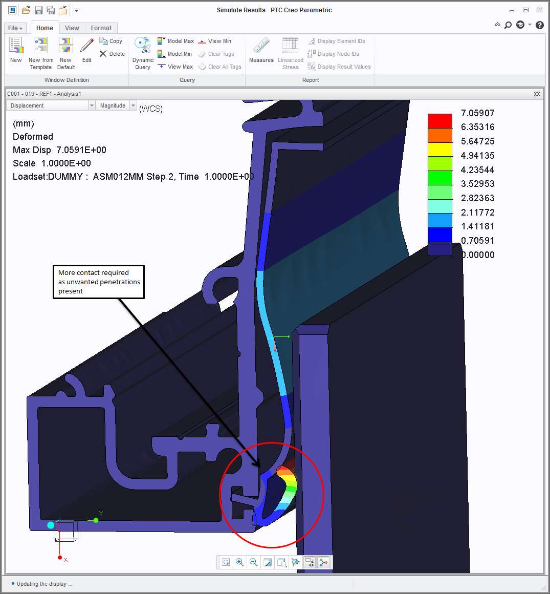
Had a quick try with the above mods, and made up materials similar to notes in earlier posts (none in model)
I ran in Creo 3 (for convenience). but used only functionality you have. Mesh used leaves a lot to be desired, contact pressures (if required will be difficult to converge, contact forces could be achieved reasonably. Run time with lots of defaults, 20 mins elapsed. Movements, as expected, are large, the initial interpenetration of the lower lip is big ...
Atb
- Mark as New
- Bookmark
- Subscribe
- Mute
- Subscribe to RSS Feed
- Permalink
- Notify Moderator
First of all, this is a problem that needs to take contact AND large deformations into account, and this is not available in ProEWF5/Creo Elements Pro, Only in Creo1 and later.
The problem is close to plane strain. I would start by using symmetry and creating a "half 2D-model", and I would exclude the complex geometry that has a limited effect on the deformation of the seal.
2D is helpful in nonlinear analysis where the analysis time can be considerable otherwise.
If I manage to get the 2D analysis through, I might continue to create a 3D-model. In that case, consider using Creo's "mapped mesh" functionality where possible; brick/wedge elements converge faster than the tet's.
When running large deformation analyses as in this case, with contacts, it is often easier to use prescribed displacement and create a measure for the load, rather than applying a certain load and calculating what the deformation will be. The analysis is more likely to converge/converges faster with prescribed displacements.
/Mats Lindqvist/Avalon Innovation/Sweden/
- Mark as New
- Bookmark
- Subscribe
- Mute
- Subscribe to RSS Feed
- Permalink
- Notify Moderator
Thanks all for the postings - everyone comments are very helpful. Everyone of this forum - I am honor to get to know - I am glad to be a member of this forum.
To answer the Creo/Elements Pro simulation - The client I am working with is using this release. The original plan was to give back the data and pictures of results of the FEA. To get the job done (remember the phrase "Gittter-R-Done"). I do have active maintance and do have Creo v1 - v2 - v3. I will take the advise of those that suggested to use Creo 3 and tell them the limitations of CreoElements Pro. I will tell the client, I can give you result data - but you will have to realize that you can't open the new files. Hence I can only offer pictures for now. I'm sure they will respect the issues.
Some notes to comment on about small feaures.
The 3d data came from the client and the ProE user that created the Aluminum Extrusion created one HUGE AND COMPLEX sketch to make the feature. ( I plan to educate the User of better techniques of creating the same model - but use / create more features. These additional features will provide better and easier manipulations of the 3D). Back to the topic, I will edit the model and remove all small radii as many of you have suggested.
I will make constraints as many have pointed out or has suggested.
To comment on the computation time and complexity. To start, the goal is to show Manager's - which are all non-engineers the deformation of the polypropylene part. The last design there engineer created did not have the hour glass (pot belly) feature. The narrow hour glass (pot belly) feature was my suggested solution to them to fix the problem. I just hav to prove it via these simulations.
Sorry - back to the topic, The results are more understood via pictures, So the more the picture looks like the image they have of the part / assembly the better and easier my question and answer session. On a side note, my benefit is I get to bill for the time. Yahoo - more $$$ for the wife.
Again, thanks to all for everyone comments - I believe the my problem is closed.
Regards,
Dave Maloy
- Mark as New
- Bookmark
- Subscribe
- Mute
- Subscribe to RSS Feed
- Permalink
- Notify Moderator
David,
Could the client load Creo View?
This would enable you to output model info and analysis results and they coutd review that way?
It would augment any paper delivery you intend.
Regards
Charles
- Mark as New
- Bookmark
- Subscribe
- Mute
- Subscribe to RSS Feed
- Permalink
- Notify Moderator
Hi all,
I've spent a couple of days working on a similar problem - a push-fit seal between some relatively stiff components and a much softer seal profile.
I've successfully used contact-only to design a free shape for the seal extrusion which gives a reasonable-looking contact pressure distribution when installed. However, my challenge is now to evaluate its resistance to being pulled out (using a retaining lip rather than relying on friction; I've assumed frictionless contact so far).
Unfortunately I'm pretty sure that I need to use LDA to get convincing results, and that flatly refused to run when I have "initial interpenetration" (which as mentioned above is an integral part of the design). Even if I tweak the seal profile back to its as-installed shape (no interpenetration), I still can't get contact+LDA to converge with any force that warrants the use of LDA, i.e. comes anywhere near to pulling it out.
I'm in Creo 2 using a 2D plane strain analysis, automesh with a max element size (have tried varying it extensively), and manual contact pairs.
- Does Creo 3 have any enhancements that would help?
- If I change to a forced-displacement analysis, can I recover a force component as a graph against displacement and read the peak force from that?
- Any other suggestions?
Thanks!
- Mark as New
- Bookmark
- Subscribe
- Mute
- Subscribe to RSS Feed
- Permalink
- Notify Moderator
Jonathan,
I would try forced displacement analysis. This converges more easily, and yes, you can create a reaction force measure that tracks the force you need to apply. LDA+contact+enforced displacement can't start with a deformed geometry. You will need to start fom an "un-assembled" state and enforce displacements so that you finally reach the positions of your stiff components that you desire, and this will hopefully include the deformed state of your flexible seal.
Here's a picture where I have used plasticity+LDA+enforced displacement to find the collapse load for a 2-memeber truss-structure. I apply the load at the top of the structure through an enforced displacement constraint. As the enforced displacement increases, the reaction force first increases until it reaches the collapse load of about 9500 N. As the displacement increases beyond this, the force drops as the structure collapses. This would be difficult to detect had the load been applied as an increasing load. The solver can't converge once the collapse load is reached and you try to increase the force further.
This was a quick'n dirty example I set up for educational purposes, so mesh/time-step is somewhat crude.
And as you probably know, contacts are frictionless, you can look up the contact force, and multiply with coefficient of friction to get an estimate of the tangential forces.
/Mats L/
- Mark as New
- Bookmark
- Subscribe
- Mute
- Subscribe to RSS Feed
- Permalink
- Notify Moderator
Thanks, Mats!
I'm working on running this version now.
I can't easily use displacements to assemble it as I want to test the disassembly mode (I'd presumably have to create several enforced displacements with custom disp-time functions, so that it first pushed the parts together and then reversed the one I want to pull out.
Therefore I've stuck with my 'as-fitted' model, and I'm now trying to find the necessary mesh size and number of steps to make it converge with larger amounts of pull-out; I've successful tested the principle with a small displacement, but it initially failed with larger movements (i.e., into the 'critical' zone!).
- Mark as New
- Bookmark
- Subscribe
- Mute
- Subscribe to RSS Feed
- Permalink
- Notify Moderator
I have not seen your model but from the description it sounds like you are trying to model some kind of lip seal that "flips over" as you reverse the motion direction. Is that correct? I've tried to sketch something here: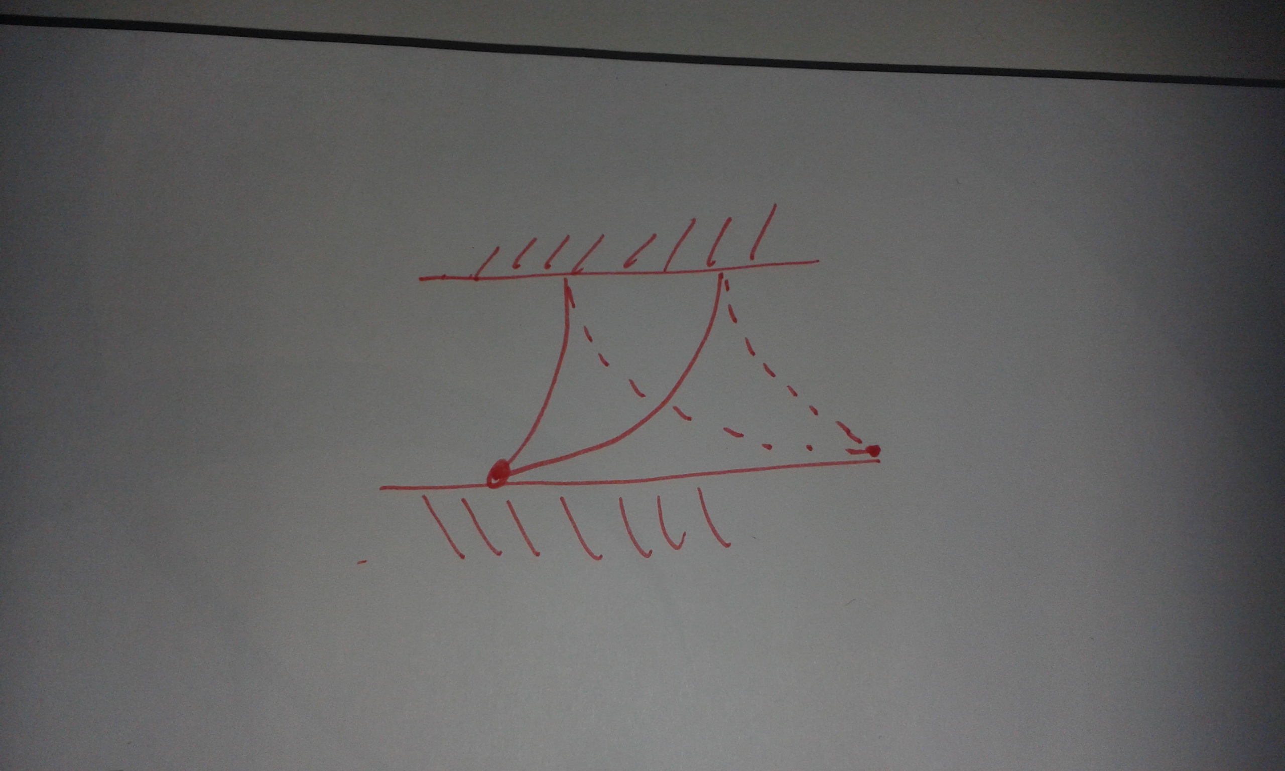
- Mark as New
- Bookmark
- Subscribe
- Mute
- Subscribe to RSS Feed
- Permalink
- Notify Moderator
Hi Mats,
No, it's nothing that complex - just a push-fit where the cavity is slightly larger than the entrance, so the seal has to be deformed to either fit or remove the 'harder' component.
I'm currently trying random combinations of number of steps and mesh size to get round "An internal engine error has occurred" - usually during the last time-step of Pass 2! ![]()
- Mark as New
- Bookmark
- Subscribe
- Mute
- Subscribe to RSS Feed
- Permalink
- Notify Moderator
Here's a seal that undergoes a deformation cycle. The seal contact is simply modeled as a constraint. I had some convergence issues at the tip; there is a singularity. So I made a surface region with linear properties just at the tip. I also ran it as a "quick check" to save time. It is possible that the convergence is more problematic if the analysis is run as SPA. Since it is 2D you can have a dense mesh and run it as "quick check" to overcome convergence issues in pass 2.
Run the analysis, and create a graph showing the Fy reaction force measure vs. time.
I hope it helps somehow...
- Mark as New
- Bookmark
- Subscribe
- Mute
- Subscribe to RSS Feed
- Permalink
- Notify Moderator
Thanks, the 'dense mesh and quick check' idea is a good one. I'll try that later this afternoon.
- Mark as New
- Bookmark
- Subscribe
- Mute
- Subscribe to RSS Feed
- Permalink
- Notify Moderator
OK, it's now working fairly well.
Localized Mesh Refinement is pretty much guaranteed to prevent convergence, whilst SPA works some of the time. Quick Check is obviously the most likely to work.
I've manually set my loadsteps (9) to follow a ^0.5 curve, giving finer steps as the displacement increases.
The final limitation on convergence seems to be the point at which the pull-out force starts to drop - I've ended up first letting it fail, noting the timestep at which is fails and adjusting the displacement value to just below that value, although with SPA this has been requiring several attempts (per design iteration!).
I've also done some investigation on run-time, trying SPA and Quick Check with varying general mesh size (note that my rads, ~0.5 mm, were set to have 5 nodes around 90° in all cases):
- 5mm mesh, SPA: 124 sec
- 3mm mesh, SPA: 199 sec
- 2mm mesh, SPA: 217 sec
- 1.5mm mesh, SPA: 155 sec
- 1mm mesh, SPA: >1200 sec (aborted)
- 3mm mesh, QC: 141 sec
- 1.5mm mesh, QC: 77 sec
- 1.2mm mesh, QC: 151 sec
- 1mm mesh, QC: 72 sec
- 0.5mm mesh, QC: 250 sec!
So, finer mesh can help convergence and actually give a faster run in some cases - but it's not a continuous function, as shown by the 1.2 mesh size QC, which I tried after the 1.0 and 1.5 runs.
Results (peak pull-out force) were quite consistent regardless of mesh size, with the SPA predicting about a 5% lower value.
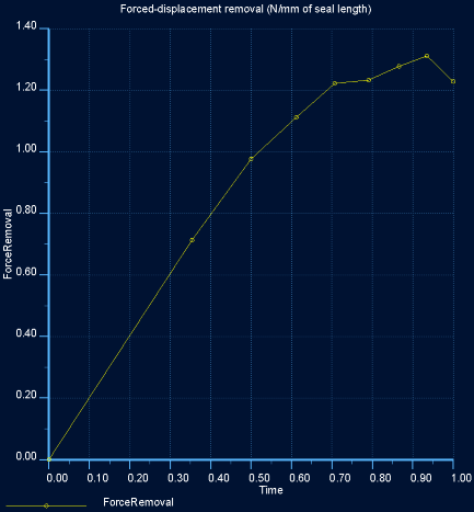
Thanks again for the pointers!
- Mark as New
- Bookmark
- Subscribe
- Mute
- Subscribe to RSS Feed
- Permalink
- Notify Moderator
Hello, Mats,
Thank you for that file, just as interesting as the others.
Best Regards.
Denis.
- Mark as New
- Bookmark
- Subscribe
- Mute
- Subscribe to RSS Feed
- Permalink
- Notify Moderator
Wow, I didn't expect this to be possible in Mechanica (or whatever its called these days).
Just a thought: since the contacts in Mechanica are frictionless (I trust Mats' statement), then making a model where the glass plate has forced displacement in y-direction with value of half glass thickness would give the same results as the more complicated sliding of the glass. (This may be done in Mats' plane strain model already, I didn't open it).


