Community Tip - Your Friends List is a way to easily have access to the community members that you interact with the most! X
- Community
- Creo+ and Creo Parametric
- 3D Part & Assembly Design
- Re: Using a sub-assembly with Degrees of Freedom (...
- Subscribe to RSS Feed
- Mark Topic as New
- Mark Topic as Read
- Float this Topic for Current User
- Bookmark
- Subscribe
- Mute
- Printer Friendly Page
Using a sub-assembly with Degrees of Freedom (Mechanism)
- Mark as New
- Bookmark
- Subscribe
- Mute
- Subscribe to RSS Feed
- Permalink
- Notify Moderator
Using a sub-assembly with Degrees of Freedom (Mechanism)

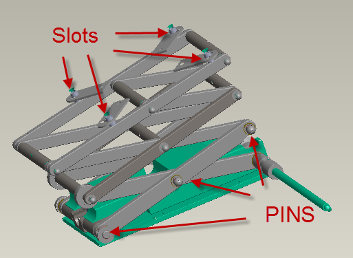
Ok, I have the perfect example for mechanisms but I have some questions for the experts. I was able to model this up so the jack moves as it should. The plates at the top are in a slot (ideally) and I wanted to leave them free to move about in the slot. I am going to have 4 of these jacks in my next higher assembly. When I've played with this in the next higher, I ran into numerous regeneration issues and issues solving for placement. Only if I move the items near where I wanted did they snap right into place. There is a unit that sits on this and aligns to the holes on those 4 plates on the top.
- Can 4 different instances of this jack be positioned to show different heights? Do I need to apply flexibility on top of the mechanism as well?
- My thought was that I could constrain the 4 holes (inserts) on each plate to the unit that sits on top of it (assembled later). Is this not correct? Does the order in which you put this jack in matter? Logic would dictate that you place the jack and then assembly the unit to it. Do I have to put the unit in mid air and assembly the jack underneath it?
- Is there a place beyond training classes that discusses best practices? I have numerous cases when subs are relly mechanisms but statically positioned in upper assemblies. This helps keep down on copied models in my system.
This thread is inactive and closed by the PTC Community Management Team. If you would like to provide a reply and re-open this thread, please notify the moderator and reference the thread. You may also use "Start a topic" button to ask a new question. Please be sure to include what version of the PTC product you are using so another community member knowledgeable about your version may be able to assist.
- Labels:
-
Assembly Design
- Mark as New
- Bookmark
- Subscribe
- Mute
- Subscribe to RSS Feed
- Permalink
- Notify Moderator
I get regen errors all the time on mechanisms. It is only happy when the part is near the position when the analysis is run. I am not an expert at this and would also like to know how to achieve a reset to avoid errors.
You might need to deploy family tables on the mounting tabs on the top. You should also be able to have a different elevation set for each of the family table jack assemblies as well.
I don't envy you for what you are trying to do. Mechanism is cool but not every application justifies the time it takes to set up the simulation. Not to mention the horsepower needed in the computer to make it interactive.
I look forward to more useful responses from others.
- Mark as New
- Bookmark
- Subscribe
- Mute
- Subscribe to RSS Feed
- Permalink
- Notify Moderator
Since there are no exact details of how jack is designed and what constraints / connections you used, I'll try some general answers.
1. Several instances of subassembly with mechanism definitely can reside in same assembly and have different shapes. Do not try to apply "flex component" (or family table) on it to adjust positions - this should be done by proper assemblying of the subassembly to the higher assembly, sometimes with several connection sets.
Simples example is "piston-rod" subassembly - it repeats 4 times in regular engine each time in different positon. This is achived by having Pin connection between Piston and Rod, and placing subassembly by 2 sets : by Cyliner - to engine block hole, and by another Cylinder to Shaft.
Each time you add 2nd (and more) occurance of mechanism subassembly into the top assembly it automatically "flexes" all connections so that independent movement could occure in each instance.
2. As you say - try to follow assembly sequence. If you first assemble jack and then position something on it - model it in the same order. Just be sure by placing this unit you do not "lock" degreees of freedom of the jack. Means do not constraint this unit to anything besides the elements of the jack.
In complicted cases you can use Mechanism application and run DOF measurement to see you still have desired # of DOFs.
3. When you create a connection and run into an error like "connection can not be created" always check that you select reference from another body (different component is not necessarily different body). For simple preview, use Mechanism Tree / Body folder, it does highlight existign bodies in simplest way.
- Mark as New
- Bookmark
- Subscribe
- Mute
- Subscribe to RSS Feed
- Permalink
- Notify Moderator
Vladimir... how do we get rid of the "disconnected" errors from gear relations? When you run the Mechanism analysis, the yellow regenerated light comes on. When you regen, you get disconnected and can no longer move components. It almost seems circular. There is just some logic in the process that isn't clear. Is there a good document somewhere that helps clear this common issue up?


