Turn on suggestions
Auto-suggest helps you quickly narrow down your search results by suggesting possible matches as you type.
Showing results for
Please log in to access translation
Turn on suggestions
Auto-suggest helps you quickly narrow down your search results by suggesting possible matches as you type.
Showing results for
- Community
- Creo+ and Creo Parametric
- 3D Part & Assembly Design
- Re: Variable-pitch-Spring assembly with constant n...
Translate the entire conversation x
Please log in to access translation
Options
- Subscribe to RSS Feed
- Mark Topic as New
- Mark Topic as Read
- Float this Topic for Current User
- Bookmark
- Subscribe
- Mute
- Printer Friendly Page
Variable-pitch-Spring assembly with constant number of ring (coil)
Dec 04, 2014
04:47 AM
- Mark as New
- Bookmark
- Subscribe
- Mute
- Subscribe to RSS Feed
- Permalink
- Notify Moderator
Please log in to access translation
Dec 04, 2014
04:47 AM
Variable-pitch-Spring assembly with constant number of ring (coil)
I am trying to assembly a spring with Dia0,7mm wire dia of 5,75 coils. The first and last coil pitch is 0,7mm and other 3 coils has 3,07-mm-pitch. I cannot assembly it to the subassembly with flexible varied items. I used relation for to keep constant of pitch however during assembly it cannot be regenareted. Does anyone know what the solution is?
This thread is inactive and closed by the PTC Community Management Team. If you would like to provide a reply and re-open this thread, please notify the moderator and reference the thread. You may also use "Start a topic" button to ask a new question. Please be sure to include what version of the PTC product you are using so another community member knowledgeable about your version may be able to assist.
Solved! Go to Solution.
ACCEPTED SOLUTION
Accepted Solutions
Dec 08, 2014
11:35 AM
- Mark as New
- Bookmark
- Subscribe
- Mute
- Subscribe to RSS Feed
- Permalink
- Notify Moderator
Please log in to access translation
Dec 08, 2014
11:35 AM
Nurdan,
Take a look at the attached model. It automatically calculates the proper pitch to maintain the intended coil count. I also tied the spring geometry to the first sketch, so you can directly edit that instead of the helical sweep. Total number of turns is still controlled by the "N" parameter.
Figuring out the equation was quite challenging due to the transition zone between the initial collapsed coil and the center section. Basically the pitch of the first coil is known (pitch = wire diameter) and the pitch of the transition area is an average of the first coil pitch and the center section pitch (pitch = [first coil pitch + center coils pitch] / 2). The trick is finding a value for the center section pitch that when combined with the first coil pitch and the transition area pitch yields the exact coil count needed. The equation ends up looking like this:
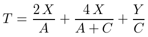
T = Total Number of Turns
X = Height of first coil (typically the coil diameter)
Y = Height of center section coils
A = Pitch of first coil (typically the coil diameter)
C = Pitch of the center section
Solving the equation for the unknown, pitch "C", yields this equation:
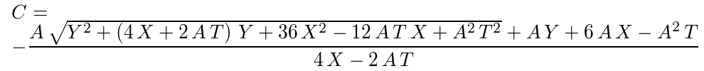
Implemented into Creo, it's working great, but now I think I'm ready to go watch Antonio's spring technique. This was too much work!
24 REPLIES 24
Dec 04, 2014
05:48 PM
- Mark as New
- Bookmark
- Subscribe
- Mute
- Subscribe to RSS Feed
- Permalink
- Notify Moderator
Please log in to access translation
Dec 04, 2014
05:48 PM
Welcome to the forum, Nurdan.
I think we need to better understand the problem before we can offer a solution.
Can you share a picture of what you are trying to achieve... maybe attach the failed assembly model?
I am not understanding if you are also varying the spring, or just other components in the assembly.
Is the spring suppose to follow the varied items in the sketch?
Dec 05, 2014
07:32 AM
- Mark as New
- Bookmark
- Subscribe
- Mute
- Subscribe to RSS Feed
- Permalink
- Notify Moderator
Please log in to access translation
Dec 05, 2014
07:32 AM
Thanks Antonius.
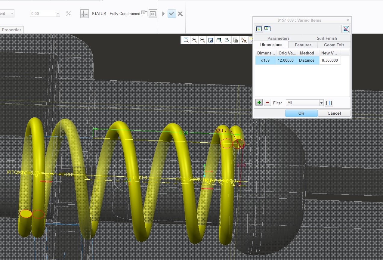
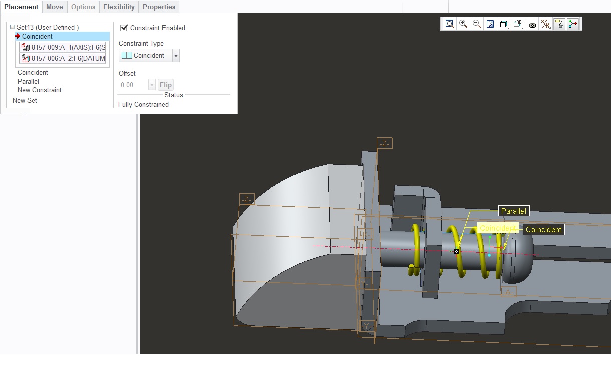
I attached pics for the clarification. All I did was to model a simple closed and ungrounded spring and add free length as variable item. new variable length is the distance between two planes. other components are fixed, just the spring is flexible.
Dec 04, 2014
09:28 PM
- Mark as New
- Bookmark
- Subscribe
- Mute
- Subscribe to RSS Feed
- Permalink
- Notify Moderator
Please log in to access translation
Dec 04, 2014
09:28 PM
Flexibility doesn't do anything to a model that you can't do in the model itself. Essentially you are creating a second copy of the model (hidden family table instance) with some dimension or parameter changed. Can you open the model by itself and make the same change to it that you are attempting to make with the flexible varied item? If not, then flexing it isn't going to work.
With a spring, if you want to simulate what the spring would look like in the compressed state, then the pitch must necessarily change. Instead of using a fixed pitch for the two sections, you need to use a pitch that is based of the current length of the spring. That way when the spring is shortened (compressed), the pitch will adjust accordingly to simulate compression.
I typically model springs with two dimensions. One dimension controls the actual geometry (compressed length) and a second dimension simply controls a construction line representing the free length. The free length drives the coil count. The compressed length drives the pitch, calculated force, and visible geometry. The only time the compressed length is set different than the free length is when it's varied via flexibility.
Make sense?
Dec 05, 2014
07:39 AM
- Mark as New
- Bookmark
- Subscribe
- Mute
- Subscribe to RSS Feed
- Permalink
- Notify Moderator
Please log in to access translation
Dec 05, 2014
07:39 AM
Tom,, that's true, I cannot make the same change in the part itself individually. But, as you told, I wrote down a relation to define pitch depending on total free length and number of coil, spring model isn't the same. since it is a closed and ungrounded spring, first and the last coils should coincident to each other with the same measurement of wire dia. Pitch should then vary with the length of the spring. I couldn't achieve that also when I tried to write down relation it didn't work.
Dec 05, 2014
08:14 AM
- Mark as New
- Bookmark
- Subscribe
- Mute
- Subscribe to RSS Feed
- Permalink
- Notify Moderator
Please log in to access translation
Dec 05, 2014
08:14 AM
You are correct, the pitch for the first and last coil need to stay fixed. On the other hand, the pitch for the coils in the middle must adjust to the spring length. Take a look at the attached model. This will maintain the coil count but adjust the pitch based on the compressed length.
Dec 05, 2014
09:54 AM
- Mark as New
- Bookmark
- Subscribe
- Mute
- Subscribe to RSS Feed
- Permalink
- Notify Moderator
Please log in to access translation
Dec 05, 2014
09:54 AM
Tom that's great. But the relation is too complicated, I tried to write a relation like this once but then think that there should be an easy way.
Anyway, it works for me however I can only change the variables ib edit position but cannot model it by myself. Because the feature seems as protrusion not sweep. So I cannot see the pitch points there. Which version do you use? mine is Creo 2.0 M050.
Dec 05, 2014
10:02 AM
- Mark as New
- Bookmark
- Subscribe
- Mute
- Subscribe to RSS Feed
- Permalink
- Notify Moderator
Please log in to access translation
Dec 05, 2014
10:02 AM
Switch to the layer tree and unhide the "construction" layer. I have a bunch of things hidden.
I used additional sections to make the transition from one pitch to another look more realistic.
Are you willing to upload your model? I'm willing to take a look at it. (attachments can be added with the advanced editor)
Dec 05, 2014
10:09 AM
- Mark as New
- Bookmark
- Subscribe
- Mute
- Subscribe to RSS Feed
- Permalink
- Notify Moderator
Please log in to access translation
Dec 05, 2014
10:09 AM
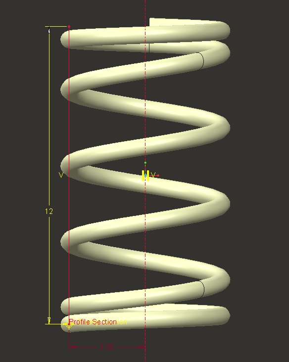
Here is my model. My inputs are;
# of coils : 5,75
Free length : 12
assemblied distance : 8,36 (from the two end points of the spring)
I put some relations.
Dec 05, 2014
02:25 PM
- Mark as New
- Bookmark
- Subscribe
- Mute
- Subscribe to RSS Feed
- Permalink
- Notify Moderator
Please log in to access translation
Dec 05, 2014
02:25 PM
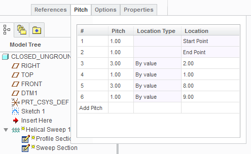
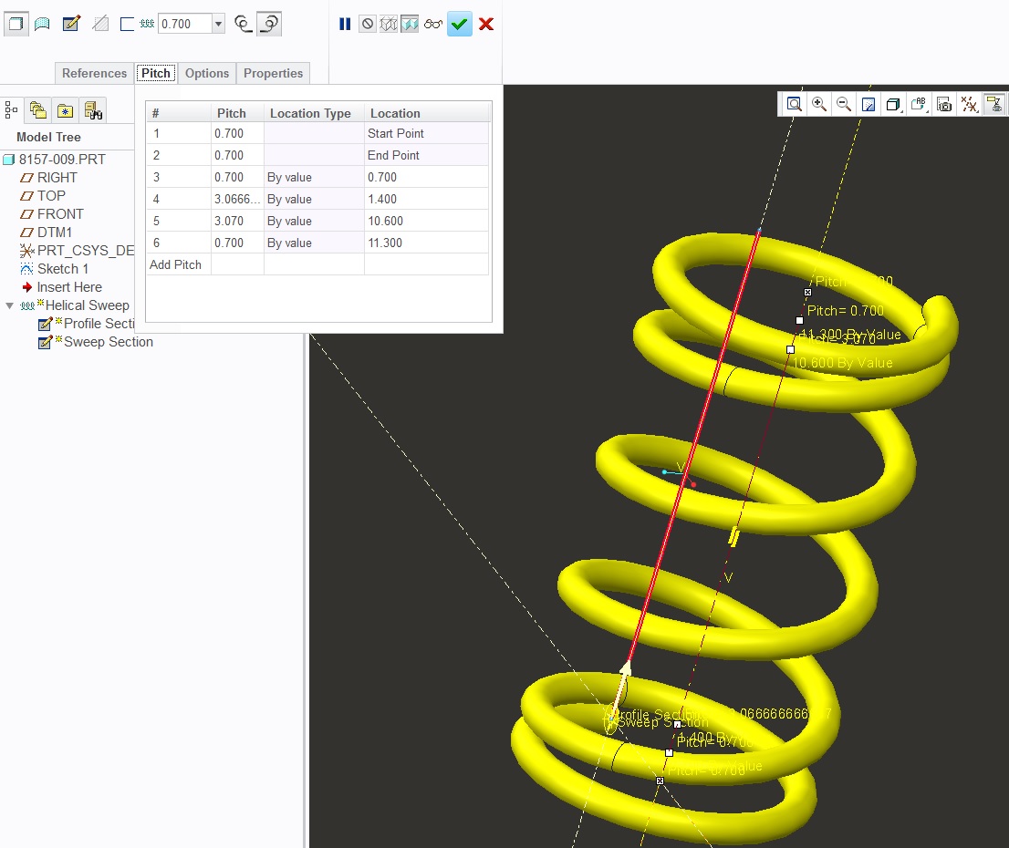
Your model is not conducive to changing the free length. your pitch locations are locking the minimum length.
I am not a fan of the pitch dialog within helical sweeps. to make this dynamic, you would have to tie each one of those location values to some relation.
I have adopted different methods for making highly dynamic springs.
Have a look:
Dec 05, 2014
03:27 PM
- Mark as New
- Bookmark
- Subscribe
- Mute
- Subscribe to RSS Feed
- Permalink
- Notify Moderator
Please log in to access translation
Dec 05, 2014
03:27 PM
Did you ever get an answer on the SPR for bad wraps?
Dec 05, 2014
03:40 PM
- Mark as New
- Bookmark
- Subscribe
- Mute
- Subscribe to RSS Feed
- Permalink
- Notify Moderator
Please log in to access translation
Dec 05, 2014
03:40 PM
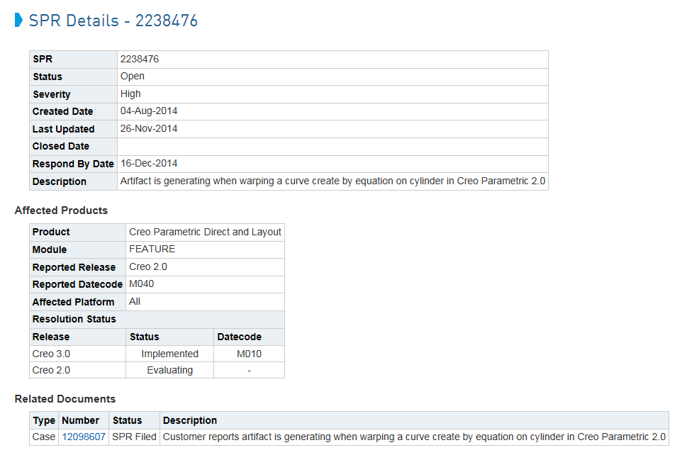
SPR 2238476
https://support.ptc.com/appserver/cs/view/spr.jsp?n=2238476
Reported as implemented in Creo 3.0 M010, and still evaluating in Creo 2.0.
Confirmation of a Creo 3.0 M010 implementation appreciated... anyone?
Dec 05, 2014
03:43 PM
- Mark as New
- Bookmark
- Subscribe
- Mute
- Subscribe to RSS Feed
- Permalink
- Notify Moderator
Please log in to access translation
Dec 05, 2014
03:43 PM
SPR is not customer viewable. (Yes, I have maintenance.) Probably just setup for you to see.
Dec 05, 2014
03:54 PM
- Mark as New
- Bookmark
- Subscribe
- Mute
- Subscribe to RSS Feed
- Permalink
- Notify Moderator
Please log in to access translation
Dec 05, 2014
03:54 PM
Not a lot to see...
Jan 28, 2015
12:24 PM
- Mark as New
- Bookmark
- Subscribe
- Mute
- Subscribe to RSS Feed
- Permalink
- Notify Moderator
Please log in to access translation
Jan 28, 2015
12:24 PM
CS reported this issue fixed in Creo 2.0 M150. It is not self healing. You have to redefine the wrap feature to remove the artifact.
Hi Tom,
This is in reference to case C12098607, regarding “artifact when warping a curve create by equation on cylinder”.
This issue was reported to R&D under SPR 2238476 and has been corrected in Creo Parametric 2.0 M150. However fix will not directly correct the issue in part uploaded to case. Once you will create a new curve, wrap and sweep, fix will correct the geometry.
Dec 08, 2014
11:45 AM
- Mark as New
- Bookmark
- Subscribe
- Mute
- Subscribe to RSS Feed
- Permalink
- Notify Moderator
Please log in to access translation
Dec 08, 2014
11:45 AM
Yes, I had checked your previous discussion on wrap. but seemed to be so complex. Actually in my company, engineers encouraged to solve problems like this in the easiest way since any engineer is not in the same standart of Creo knowledge. so wrap feature is not very encouraged..
Dec 08, 2014
12:32 PM
- Mark as New
- Bookmark
- Subscribe
- Mute
- Subscribe to RSS Feed
- Permalink
- Notify Moderator
Please log in to access translation
Dec 08, 2014
12:32 PM
I find the wrap method to be the easiest to create a spring on the fly and very forgiving.
I also have a need for the spring to remain dynamic for illustration so the variable pitch helical sweep is not an simple option.
The only issue I found was wrap is with equation curves and likely splines. But with lines and arcs, no issues.
Dec 08, 2014
12:41 PM
- Mark as New
- Bookmark
- Subscribe
- Mute
- Subscribe to RSS Feed
- Permalink
- Notify Moderator
Please log in to access translation
Dec 08, 2014
12:41 PM
I was actually just reading this:
http://communities.ptc.com/message/265662#265662
Though not geometrically correct, still pretty cool.
Dec 08, 2014
12:44 PM
- Mark as New
- Bookmark
- Subscribe
- Mute
- Subscribe to RSS Feed
- Permalink
- Notify Moderator
Please log in to access translation
Dec 08, 2014
12:44 PM
Definitely a nice solution for animations.
Dec 08, 2014
12:45 PM
- Mark as New
- Bookmark
- Subscribe
- Mute
- Subscribe to RSS Feed
- Permalink
- Notify Moderator
Please log in to access translation
Dec 08, 2014
12:45 PM
It's more correct than you might suspect. It maintains a constant material volume for the spring and changes the diameter. The larger the number of pieces, the more closely it approximates the actual behavior of shear deflection.
Dec 08, 2014
11:35 AM
- Mark as New
- Bookmark
- Subscribe
- Mute
- Subscribe to RSS Feed
- Permalink
- Notify Moderator
Please log in to access translation
Dec 08, 2014
11:35 AM
Nurdan,
Take a look at the attached model. It automatically calculates the proper pitch to maintain the intended coil count. I also tied the spring geometry to the first sketch, so you can directly edit that instead of the helical sweep. Total number of turns is still controlled by the "N" parameter.
Figuring out the equation was quite challenging due to the transition zone between the initial collapsed coil and the center section. Basically the pitch of the first coil is known (pitch = wire diameter) and the pitch of the transition area is an average of the first coil pitch and the center section pitch (pitch = [first coil pitch + center coils pitch] / 2). The trick is finding a value for the center section pitch that when combined with the first coil pitch and the transition area pitch yields the exact coil count needed. The equation ends up looking like this:
T = Total Number of Turns
X = Height of first coil (typically the coil diameter)
Y = Height of center section coils
A = Pitch of first coil (typically the coil diameter)
C = Pitch of the center section
Solving the equation for the unknown, pitch "C", yields this equation:
Implemented into Creo, it's working great, but now I think I'm ready to go watch Antonio's spring technique. This was too much work!
Dec 08, 2014
11:43 AM
- Mark as New
- Bookmark
- Subscribe
- Mute
- Subscribe to RSS Feed
- Permalink
- Notify Moderator
Please log in to access translation
Dec 08, 2014
11:43 AM
Tom, it is a really impressive work. Really glad you worked for that!
Thanks for your excellent work. I'll check out your model.
Dec 08, 2014
11:53 AM
- Mark as New
- Bookmark
- Subscribe
- Mute
- Subscribe to RSS Feed
- Permalink
- Notify Moderator
Please log in to access translation
Dec 08, 2014
11:53 AM
Very impressive, Tom! 
Dec 05, 2014
02:36 PM
- Mark as New
- Bookmark
- Subscribe
- Mute
- Subscribe to RSS Feed
- Permalink
- Notify Moderator
Please log in to access translation
Dec 05, 2014
02:36 PM
Wow Tom, that must be a WF4 or earlier version. Never seen the graph driven pitch of the XTOP menu.
Dec 05, 2014
02:58 PM
- Mark as New
- Bookmark
- Subscribe
- Mute
- Subscribe to RSS Feed
- Permalink
- Notify Moderator
Please log in to access translation
Dec 05, 2014
02:58 PM
Lol. That's how WF5 does it for variable pitch helical sweeps!
I had never seen the new way until today when I opened Nurdan's part in Creo 2 (we're still on WF5 for production).