
Turn on suggestions
Auto-suggest helps you quickly narrow down your search results by suggesting possible matches as you type.
Showing results for
Please log in to access translation
Turn on suggestions
Auto-suggest helps you quickly narrow down your search results by suggesting possible matches as you type.
Showing results for
Translate the entire conversation x
Please log in to access translation
Options
- Subscribe to RSS Feed
- Mark Topic as New
- Mark Topic as Read
- Float this Topic for Current User
- Bookmark
- Subscribe
- Mute
- Printer Friendly Page
Weld Note
Jan 04, 2013
11:25 AM
- Mark as New
- Bookmark
- Subscribe
- Mute
- Subscribe to RSS Feed
- Permalink
- Notify Moderator
Please log in to access translation
Jan 04, 2013
11:25 AM
Weld Note
Is there a way to force a carriage return in a weld note reference? Right now I just have a second note near the weld note. If not, is there a way to relate this annotation to the weldnote instead of to the view?
This thread is inactive and closed by the PTC Community Management Team. If you would like to provide a reply and re-open this thread, please notify the moderator and reference the thread. You may also use "Start a topic" button to ask a new question. Please be sure to include what version of the PTC product you are using so another community member knowledgeable about your version may be able to assist.
Solved! Go to Solution.
Labels:
- Labels:
-
Weld Design
ACCEPTED SOLUTION
Accepted Solutions
Jan 09, 2013
08:51 AM
- Mark as New
- Bookmark
- Subscribe
- Mute
- Subscribe to RSS Feed
- Permalink
- Notify Moderator
Please log in to access translation
Jan 09, 2013
08:51 AM
After copying and editing the original symbol, adding the /REFERENC2/, and adjusting the spacing how I would like I had to do the following steps for get the text to show up in the appropriate boxes for the weld note.
(WF5/Creo)
1. In the Annotate Tab, under Format, select Symbol Gallery
2. Redefine, Retrieve, select the name of the symbol you're modifying, Open
I had to put the \REFERENC2\ in the correct groups in order for it to appear only where it was supposed appear.
3. Select Groups, Change Level (I needed to added to all three levels: ARROW_SIDE, OTHER_SIDE, STAGGERD)
4. Select Edit, Arrow_Side, Add, select one \REFERENC2\ hold the Ctrl key and select the other, select OK
These needed to go down several levels.
5. Select Change Level, select Arrow_Side
6. Select Edit, Leader_Orientation, Add, select one \REFERENC2\ hold the Ctrl key and select the other, select OK
7. Select Change Level, select Leader_Orientation
8. Select Edit, Left, Add, select one \REFERENC2\ hold the Ctrl key and select the other, select OK
9. Select Change Level, select Left
10. Select Edit, Reference, Add, select one \REFERENC2\ hold the Ctrl key and select the other, select OK
This completed adding the second line to one of the fields.
11. Select UP, repeat steps 7-10 for putting the second line on the Right
12. Select UP until you get to Arrow_Side, Other_Side, Staggered
13. Repeat 5-11 for the Left and Right of Other_Side
14. Repeat 5-11 for the Left and Right of Staggerd
15. Done, Done, Write, Pick Inst - (Select the name of the symbol your modifying), (Enter - to select the current directory).
16. Test to make sure you got it done correctly.
Results: See below.
33 REPLIES 33
Jan 04, 2013
11:30 AM
- Mark as New
- Bookmark
- Subscribe
- Mute
- Subscribe to RSS Feed
- Permalink
- Notify Moderator
Please log in to access translation
Jan 04, 2013
11:30 AM
Or, is there a way to place this above the weld note line as shown here.
Jan 04, 2013
11:41 AM
- Mark as New
- Bookmark
- Subscribe
- Mute
- Subscribe to RSS Feed
- Permalink
- Notify Moderator
Please log in to access translation
Jan 04, 2013
11:41 AM
I have noticed some serious inconsistencies in the weld symbols. I might suggest you edit the weld symbol to your liking, including adding additional text feature.
You might copy the original to your own library so that updates won't undo all you hard work.
I think the idea of relating free floating text to a another annotation feature is brilliant! Care to write that up as an idea? I doubt it is possible today but I will test it.
Jan 04, 2013
12:16 PM
- Mark as New
- Bookmark
- Subscribe
- Mute
- Subscribe to RSS Feed
- Permalink
- Notify Moderator
Please log in to access translation
Jan 04, 2013
12:16 PM
So the reference note is one line no matter what. I guess it is like a table text entity without wrapping capability.
As for moving them together, I was able to window-select the two lines of text (and the weld symbol) and move them as a set.
I would probably opt for making the 2-line note separate text and relating it to the view... and remember to move them using the window-select.
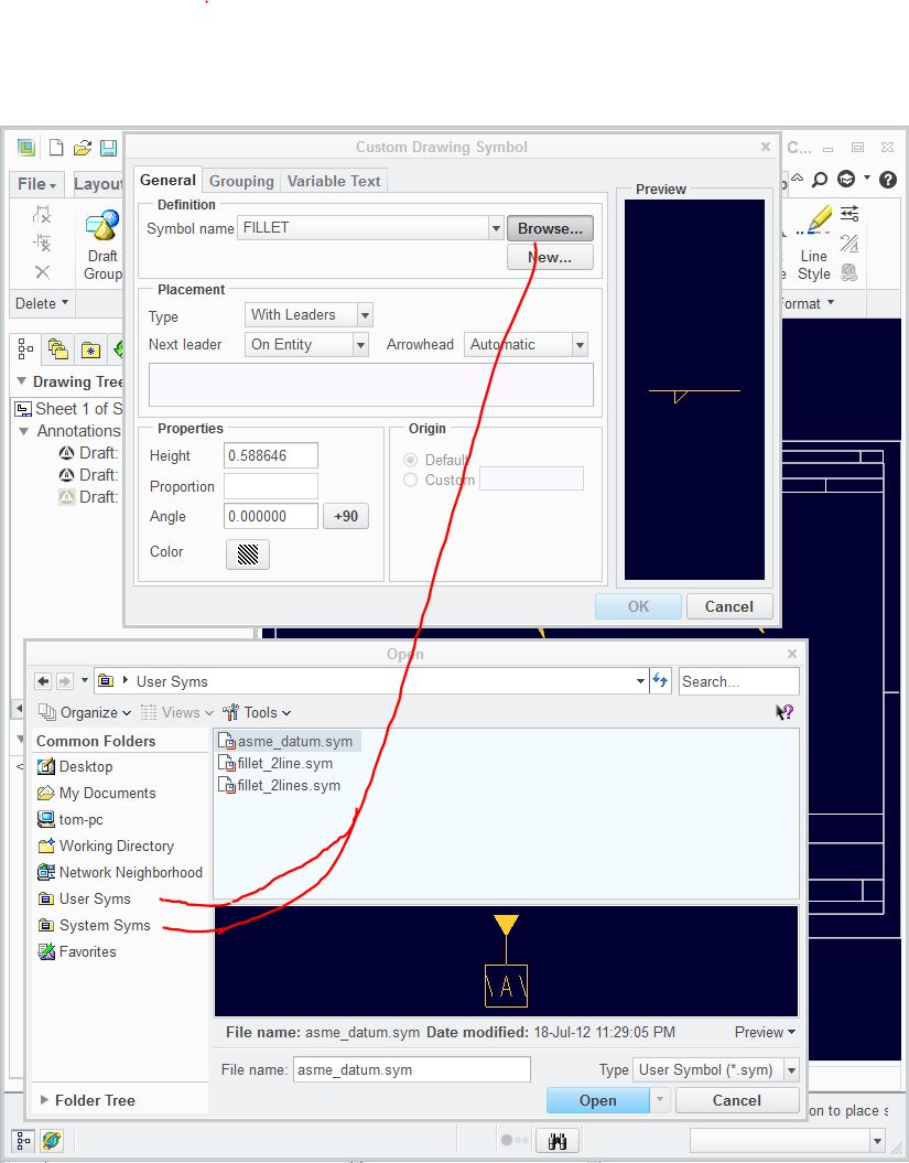
If this was indeed a common feature callout, I would definitely make my own symbol. remember that you have a quick link to custom -user- symbols folder in the left hand file selection window. This may make using custom symbols much easier if you set the config.pro option pro_symbol_dir for where to find them.
Jan 04, 2013
03:16 PM
- Mark as New
- Bookmark
- Subscribe
- Mute
- Subscribe to RSS Feed
- Permalink
- Notify Moderator
Please log in to access translation
Jan 04, 2013
03:16 PM
When you mention custom symbols, do you lose that parameters that are available in the weld note? (i.e. does the weld symbol then become a dumb symbol so that if thing change, you have to swap out symbols, or do you edit them?.)
Thanks, Dale
Jan 04, 2013
03:34 PM
- Mark as New
- Bookmark
- Subscribe
- Mute
- Subscribe to RSS Feed
- Permalink
- Notify Moderator
Please log in to access translation
Jan 04, 2013
03:34 PM
Not at all! Just save the original PTC symbol to your own folder and edit it. Symbols are very intelligent features.
I don't do this much so bare with me.
I would suggest setting up your -user- custom symbol palette folder and copy the -system- custom symbol palette to there just to have a clean set.
<loadpoint>\Creo 2.0\Common Files\M030\symbols\library_syms
In your drawing, pick Symbol/Symbol Gallary/(text menu)-Redefine/Retrieve/ and find the symbol you wish to modify. A drawing style dialog opens (oddly enough, it is a wildfire interface!) and you can now edit the symbol at will. You will also find a whole lot of other really neat things you can do with symbols.
The only thing I will warn you away from in symbols is filled polygons (filled hatch and alike) because they do cause graphic errors. You will notice that nearly all filled symbols from PTC use line elements rather than filled polygons.
Somewhere you should be able to rename the symbol. How you want to manage the files is something you will need to think about. I am sure I overlooked a few things here, but this is the jest of it.
Remember to set the -user- symbol palette location in config.pro for easy access in the symbol selection dialog.
Jan 04, 2013
06:03 PM
- Mark as New
- Bookmark
- Subscribe
- Mute
- Subscribe to RSS Feed
- Permalink
- Notify Moderator
Please log in to access translation
Jan 04, 2013
06:03 PM
I made a copy of the symbol and edited the \REFERENCE\ to include \REFERENC2\ in the same text string. For some reason, the vertical alignment in this type of text does not work well in right-justified text but I was able to make up for that with a space character. This should now work as expected with the full functionality of the original.
I did learn a lot by doing this.
1) Having a user symbol library specified really does encourage one to manage their own symbols for often used or modified default symbols.
2) You have to write out the modified symbol if you want access to it later. The system will attach a version number just like it does with part and assembly files.
3) Symbols are maintained in your work file so no problem with loosing the reference link to the original.
4) This one got me, and is still very criptic: managing groups for when things show and don't show is a PITA! For this one, I used an existing element, therefore the grouping was not affected. This can get really involved as this particular feature is used in all 3 groups and twice in each sub-group.
5) To take it one step further, you -could- enhance this with even more groups to cover 1 line or 2 lines of text. I'm not that good at it yet.

Jan 07, 2013
12:02 PM
- Mark as New
- Bookmark
- Subscribe
- Mute
- Subscribe to RSS Feed
- Permalink
- Notify Moderator
Please log in to access translation
Jan 07, 2013
12:02 PM
Did you make this file in Creo 2.0?
If so, and if you have access to WF5.0/Creo M130 or older, could you make it in that?
Or better yet, I'll probably see if you can help me create/modify the symbol to make a special 2 line reference symbol. I'll have to play around with editing it to add the \REFERENCE2 as you mentioned above. New ground for me. Thanks, Dale
Jan 07, 2013
03:18 PM
- Mark as New
- Bookmark
- Subscribe
- Mute
- Subscribe to RSS Feed
- Permalink
- Notify Moderator
Please log in to access translation
Jan 07, 2013
03:18 PM
I would not have assumed that version would have made a difference but now that you mention it, of course.
It is not that difficult. Again, I just added the variable name to text field of the \REFERENCE\ variable and relocated the text line (visually aligned with other text). All the required intelligence is already incorporated in the original text feature.
In Creo 2.0, the second line becomes offset for some reason. I had to add a space character to the second line at the end only on the left entry. I also made sure that the variable name was the same length (in characters) as \REFERENCE\ by making it \REFERENC2\. This seems to make a difference. And in the values screen, you want to put something in there like "text", again, the same length as the top line. I had a hard time keeping things positionally logical until I started watching the number of characters used for the variable and the value.
Since the interface looks like WF5.0, I think this will be a piece of cake for you. Again, just remember to write it out. These symbols remain with the part so once you get exactly what you want, write it to disk.
Jan 08, 2013
04:15 PM
- Mark as New
- Bookmark
- Subscribe
- Mute
- Subscribe to RSS Feed
- Permalink
- Notify Moderator
Please log in to access translation
Jan 08, 2013
04:15 PM
Forgive my ignorance, but I copied over the weld symbol to where my custom symbols are located and then renamed it. My question is how do I "open" it for editing? Thanks, Dale
Jan 08, 2013
04:27 PM
- Mark as New
- Bookmark
- Subscribe
- Mute
- Subscribe to RSS Feed
- Permalink
- Notify Moderator
Please log in to access translation
Jan 08, 2013
04:27 PM
I got the weldnote copied from the current note by trying to insert a note and selecting new and giving it a name. I then copied the current weldnote into it.
I am now trying to figure out how to add a new attribute (referenc2 as you suggested) to this custom symbol. Thanks, Dale
Jan 08, 2013
04:38 PM
- Mark as New
- Bookmark
- Subscribe
- Mute
- Subscribe to RSS Feed
- Permalink
- Notify Moderator
Please log in to access translation
Jan 08, 2013
04:38 PM
I wasn't using the definition dialog. I was on the field of the drawing and was able to grab the text and edit it the text editor. After I did that, the new variable showed up on the dialog.
Jan 08, 2013
04:45 PM
- Mark as New
- Bookmark
- Subscribe
- Mute
- Subscribe to RSS Feed
- Permalink
- Notify Moderator
Please log in to access translation
Jan 08, 2013
04:45 PM
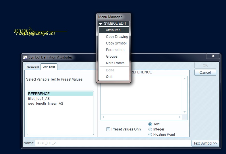
I've waded into the definition editor and have the two REFERENC2'S added (their at the bottom - that's why you can't see them) and gave them a preset value of tex2 (for both). Both - depending upon left or right reference arrow on the weldnote.
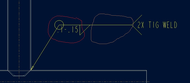
While I am here though, I have another quick question regarding the following picture.
The [.2] after weld is for two decimal places I presume.
What is the 1.1 on the next line for?
I added a second picture ( and if you look cross eyed, you can see the REFERENCE & REFERENC2 on both ends).
Jan 08, 2013
05:04 PM
- Mark as New
- Bookmark
- Subscribe
- Mute
- Subscribe to RSS Feed
- Permalink
- Notify Moderator
Please log in to access translation
Jan 08, 2013
05:04 PM
Congratulations! You are now a symbol expert 
The "1.1" is one of the default values. You can form a pick list of sorts with the preset values.
Jan 09, 2013
08:51 AM
- Mark as New
- Bookmark
- Subscribe
- Mute
- Subscribe to RSS Feed
- Permalink
- Notify Moderator
Please log in to access translation
Jan 09, 2013
08:51 AM
After copying and editing the original symbol, adding the /REFERENC2/, and adjusting the spacing how I would like I had to do the following steps for get the text to show up in the appropriate boxes for the weld note.
(WF5/Creo)
1. In the Annotate Tab, under Format, select Symbol Gallery
2. Redefine, Retrieve, select the name of the symbol you're modifying, Open
I had to put the \REFERENC2\ in the correct groups in order for it to appear only where it was supposed appear.
3. Select Groups, Change Level (I needed to added to all three levels: ARROW_SIDE, OTHER_SIDE, STAGGERD)
4. Select Edit, Arrow_Side, Add, select one \REFERENC2\ hold the Ctrl key and select the other, select OK
These needed to go down several levels.
5. Select Change Level, select Arrow_Side
6. Select Edit, Leader_Orientation, Add, select one \REFERENC2\ hold the Ctrl key and select the other, select OK
7. Select Change Level, select Leader_Orientation
8. Select Edit, Left, Add, select one \REFERENC2\ hold the Ctrl key and select the other, select OK
9. Select Change Level, select Left
10. Select Edit, Reference, Add, select one \REFERENC2\ hold the Ctrl key and select the other, select OK
This completed adding the second line to one of the fields.
11. Select UP, repeat steps 7-10 for putting the second line on the Right
12. Select UP until you get to Arrow_Side, Other_Side, Staggered
13. Repeat 5-11 for the Left and Right of Other_Side
14. Repeat 5-11 for the Left and Right of Staggerd
15. Done, Done, Write, Pick Inst - (Select the name of the symbol your modifying), (Enter - to select the current directory).
16. Test to make sure you got it done correctly.
Results: See below.
Jan 09, 2013
09:13 AM
- Mark as New
- Bookmark
- Subscribe
- Mute
- Subscribe to RSS Feed
- Permalink
- Notify Moderator
Please log in to access translation
Jan 09, 2013
09:13 AM
Wow! Didn't know I was going to get into quite the project. And yes, I feel a lot more knowledgeable about symbols, especially ones with option boxes. Don't know how to create the options, but could probably modify some of the welding ones to have many options. Thanks for your help Antonius, I probably won't have attacked that without those who have gone on before.
(Had to go back and add the Write to step 15. If you don't, you'll get to do it all over again and cement the lesson into your head, Hehehe).
Jan 09, 2013
12:20 PM
- Mark as New
- Bookmark
- Subscribe
- Mute
- Subscribe to RSS Feed
- Permalink
- Notify Moderator
Please log in to access translation
Jan 09, 2013
12:20 PM
I was working hard to avoid the multiple entries of the same thing. Either things got a lot easier in Creo 2.0 or you made it harder than you needed to. I suspect the former, of course
I did start going the route of adding new text annotations when I found I could simply modify the existing /REFERENCE/ annotation in 2 places (left and right). That annotation already had all the grouping assigned. Once added to the annotation, /REFERENC2/ was recognized as a new variable and showed up in the variable table.
Care to add your version of the symbol to a reply so I can have a look?
Jan 09, 2013
01:36 PM
- Mark as New
- Bookmark
- Subscribe
- Mute
- Subscribe to RSS Feed
- Permalink
- Notify Moderator
Please log in to access translation
Jan 09, 2013
01:36 PM
Attached is the file. Evaluate it and give feedback.
I would hope they had simplified this by now.
Thanks,
Dale
Jan 09, 2013
03:00 PM
- Mark as New
- Bookmark
- Subscribe
- Mute
- Subscribe to RSS Feed
- Permalink
- Notify Moderator
Please log in to access translation
Jan 09, 2013
03:00 PM
While you are editing the symbol, can you open the text properties of /REFERENCE/ and be presented with a the text editor? I suspect I cheated in my method, but that group and layer stuff just threw me for a loop.
I noticed that the left hand /REFERENC2/ is left justified rather than right. Is this what you were hoping for? I might suggest right justification and using spaces to move the text leftward as appropriate.
I will if I can post a video of the process I used for posterity.
Jan 09, 2013
03:07 PM
- Mark as New
- Bookmark
- Subscribe
- Mute
- Subscribe to RSS Feed
- Permalink
- Notify Moderator
Please log in to access translation
Jan 09, 2013
03:07 PM
When you talk about the left hand /REFERENC2/, do you mean the one that is on the left side of the screen, or the one that shows up with the left_sided arrow. If it is the one on the left side, I should probably edit it to be RH justified so that it would match /REFERENCE/ that is on the same side.
Jan 09, 2013
03:45 PM
- Mark as New
- Bookmark
- Subscribe
- Mute
- Subscribe to RSS Feed
- Permalink
- Notify Moderator
Please log in to access translation
Jan 09, 2013
03:45 PM
Yep, the one that is shown on the left.
If you watch carefully in the video, you will see me add a space at the end of \REFERENC2\ to keep the text right-aligned. I don't know if this is a Creo bug or if this has always been there.
The video is 50mb so I hope the server can handle it. So far, I am liking CamStudio once you get things configured.
Jan 09, 2013
03:47 PM
- Mark as New
- Bookmark
- Subscribe
- Mute
- Subscribe to RSS Feed
- Permalink
- Notify Moderator
Please log in to access translation
Jan 09, 2013
03:47 PM
Never mind, use the slider to access the full view button.
Jan 11, 2013
04:29 PM
- Mark as New
- Bookmark
- Subscribe
- Mute
- Subscribe to RSS Feed
- Permalink
- Notify Moderator
Please log in to access translation
Jan 11, 2013
04:29 PM
I show that the redefined symbol that I made now shows up in my WF5/Creo symbol folder and in the Creo 2.0 folder. You seem to run multiple versions the software, could you see if it updates (adds) the file in both symbol directories? Thanks, Dale
Jan 11, 2013
04:49 PM
- Mark as New
- Bookmark
- Subscribe
- Mute
- Subscribe to RSS Feed
- Permalink
- Notify Moderator
Please log in to access translation
Jan 11, 2013
04:49 PM
When I edited the properties on \REFERENCE\ and got the dialog box, I hit "enter" for a carriage return and then was able to add \REFERENC2\ which not only got all of the properties of the first attribute, but I did not have to do all the groupings becase it was inherent in the first text. When I did all the groupings was a result of copying and pasting the \REFERENCE\ as \REFERENC2\. This didn't allow the grouping to translate to the new attribute and I had to relink it. Your way is much simplier since I sort of wanted them to be together anyways.
But the copying and pasting would work for the other thing I was looking for (adding the text above the line) and then you would have to go through all the groupings so that it would allow the attribute to show up only at the appropriate times.
Jan 11, 2013
06:08 PM
- Mark as New
- Bookmark
- Subscribe
- Mute
- Subscribe to RSS Feed
- Permalink
- Notify Moderator
Please log in to access translation
Jan 11, 2013
06:08 PM
Creo 2 is not writing the file out anywhere but where I tell it. This could be because I set the user folder. The only thing I try to be really careful of is not overwriting default files.
Good to know WF5 also lets you do the multiple lines. I thought it should but I suppose the dialog just isn't as inviting to make you aware of it.
Jan 16, 2013
02:32 PM
- Mark as New
- Bookmark
- Subscribe
- Mute
- Subscribe to RSS Feed
- Permalink
- Notify Moderator
Please log in to access translation
Jan 16, 2013
02:32 PM
Thanks for checking. So you have only one set of weld symbols, or they each have their own path to their own symbols?
Jan 16, 2013
02:59 PM
- Mark as New
- Bookmark
- Subscribe
- Mute
- Subscribe to RSS Feed
- Permalink
- Notify Moderator
Please log in to access translation
Jan 16, 2013
02:59 PM
I have a "user" symbol library specified in config.pro and the system remembers the "default" symbol library.
pro_symbol_dir [full path]
I am finding that this is not common among other libraries. For instance, the Graphic Library is treated much differently and a config option will completely isolate the system library. I just mention this so you don't think that this is a universal way of working.
May 30, 2013
02:13 PM
- Mark as New
- Bookmark
- Subscribe
- Mute
- Subscribe to RSS Feed
- Permalink
- Notify Moderator
Please log in to access translation
May 30, 2013
02:13 PM
Are there options in the config.pro to control the length of the line (space) where the fillet size and fillet length are located?
May 30, 2013
03:04 PM
- Mark as New
- Bookmark
- Subscribe
- Mute
- Subscribe to RSS Feed
- Permalink
- Notify Moderator
Please log in to access translation
May 30, 2013
03:04 PM
That just looks like a very poorly constructed symbol feature.
Edit the symbol and see if it is constructed different from the way it presents.
The weld symbols I have worked on, this is simply sketched geometry and shouldn't change like that.
May 30, 2013
03:14 PM
- Mark as New
- Bookmark
- Subscribe
- Mute
- Subscribe to RSS Feed
- Permalink
- Notify Moderator
Please log in to access translation
May 30, 2013
03:14 PM
They are the standard, out of the box, ansi fillet weld.


