
Turn on suggestions
Auto-suggest helps you quickly narrow down your search results by suggesting possible matches as you type.
Showing results for
Please log in to access translation
Turn on suggestions
Auto-suggest helps you quickly narrow down your search results by suggesting possible matches as you type.
Showing results for
Community Tip - When posting, your subject should be specific and summarize your question. Here are some additional tips on asking a great question. X
- Community
- Creo+ and Creo Parametric
- 3D Part & Assembly Design
- Re: how do you constrain to a floor when simulatin...
Translate the entire conversation x
Please log in to access translation
Options
- Subscribe to RSS Feed
- Mark Topic as New
- Mark Topic as Read
- Float this Topic for Current User
- Bookmark
- Subscribe
- Mute
- Printer Friendly Page
how do you constrain to a floor when simulating?
Jul 27, 2013
12:20 PM
- Mark as New
- Bookmark
- Subscribe
- Mute
- Subscribe to RSS Feed
- Permalink
- Notify Moderator
Please log in to access translation
Jul 27, 2013
12:20 PM
how do you constrain to a floor when simulating?
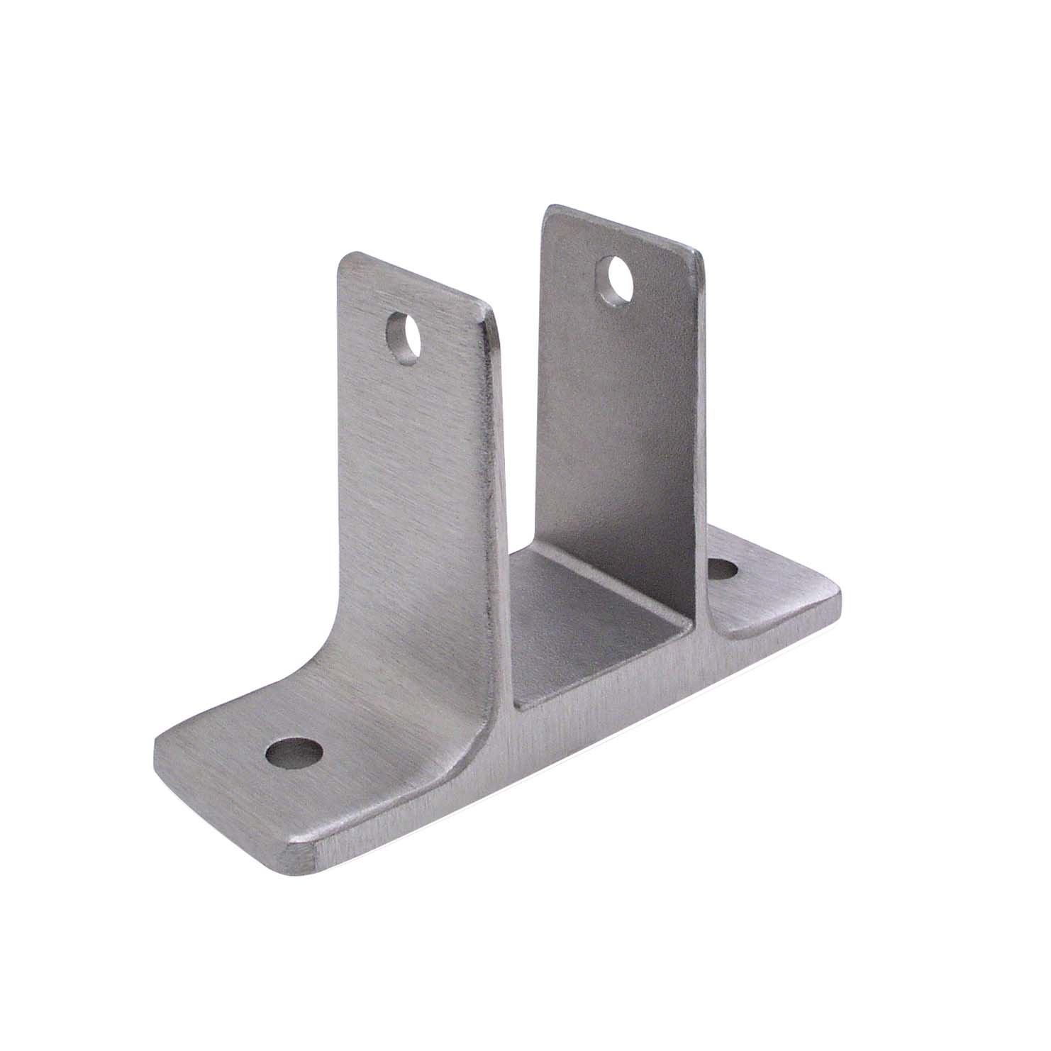
I have a simple bracket which is supposed to be bolted to a horizontal floor. See image for an example.
I would like to do some finite element analysis on the bracket.
A force is applied on the bracket vertically up.
How do I set-up the constraints properly? If I simply constraint the bottom surface of the bracket, the results are wrong, because in reality the bracket will only be constrained to the floor where the bolts are going into the floor!
If I only constrain a surface region on the top surface of the bracket where the bolt is touching the bracket, then its also no good, because in reality the bracket is unable to bend downwards (into the floor).
I would like to do it in part mode in CREO 2 simulate (and not assembly mode, where I would simply model a floor and bolt, because I only want to see deformations of the bracket).
Please help..
This thread is inactive and closed by the PTC Community Management Team. If you would like to provide a reply and re-open this thread, please notify the moderator and reference the thread. You may also use "Start a topic" button to ask a new question. Please be sure to include what version of the PTC product you are using so another community member knowledgeable about your version may be able to assist.
18 REPLIES 18
Jul 30, 2013
09:17 AM
- Mark as New
- Bookmark
- Subscribe
- Mute
- Subscribe to RSS Feed
- Permalink
- Notify Moderator
Please log in to access translation
Jul 30, 2013
09:17 AM
Hi bj p,
Have you tried modeling the floor and creating a contact analysis?
Jul 30, 2013
10:04 AM
- Mark as New
- Bookmark
- Subscribe
- Mute
- Subscribe to RSS Feed
- Permalink
- Notify Moderator
Please log in to access translation
Jul 30, 2013
10:04 AM
Yes, but how do I make the bolts and floor infinitely stiff?
Jul 30, 2013
11:26 AM
- Mark as New
- Bookmark
- Subscribe
- Mute
- Subscribe to RSS Feed
- Permalink
- Notify Moderator
Please log in to access translation
Jul 30, 2013
11:26 AM
Create a rigid link for the bolts and the floor. A rigid link prevents the part from deforming = infinitely stiff.
Jul 30, 2013
12:18 PM
- Mark as New
- Bookmark
- Subscribe
- Mute
- Subscribe to RSS Feed
- Permalink
- Notify Moderator
Please log in to access translation
Jul 30, 2013
12:18 PM
Since you want the bracket to be able to separate from the floor but not penetrate it, I think you have no choice but to create an assembly and run a contact analysis.
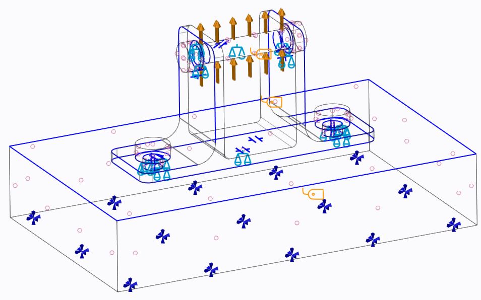
I would model the floor as a large rectangular block, and create a material for it with an appropriate elastic modulus (you could use just a large number, say 10x - 50x the modulus of the bracket, although http://www.engineeringtoolbox.com/concrete-properties-d_1223.html suggests that concrete is actually less stiff than aluminium). You could constrain the other five faces of the 'floor' to keep it well supported, although a more realistic constraint might be to lock the underside and create a mirror constraint on each of the four sides.
For a simple approach you could define a surface region on the bracket where the head of the bolt sits, and use a rigid link to connect this to the floor; really, I think you should probably look into fasteners although I have no experience of these.
When viewing results, remember that you can set Location -> By Component and isolate just the part you want to view, although I don't think there's a way to view displacements relative to an arbitrary datum.
Jul 30, 2013
01:39 PM
- Mark as New
- Bookmark
- Subscribe
- Mute
- Subscribe to RSS Feed
- Permalink
- Notify Moderator
Please log in to access translation
Jul 30, 2013
01:39 PM
Ok guys, thanks sofar..
Ive created a rigid link on the top-surface of the "floor", and constrained all other sides.
I got the following warning when the top-surface was also constrained while having the rigid link:
"The dependent side geometrical references may be in conflict with another rigid/weighted link or constraint".
I have made the floor-bolts part of the floor .prt so I dont need to create constraints for those..
So far so good.
Ive placed a simple horizontal bolt trough the bracket clevis-arms, and put a vertical force on the surface of the bolt which pulls the bracket up.
When I run a simulation I get a warning for these surfaces:
"A portion of the highlighted load/constraint is applied to an internal surface"
So how do I make CREO understand that this bolt is infinately stiff and will apply a simple force on my bracket without error?
This horizontal bolt has a head and a screw, so the clevis arms should be able to bend outwards, otherwise I would simply apply the force vertically on the clevis-arm holes.
Jul 30, 2013
04:28 PM
- Mark as New
- Bookmark
- Subscribe
- Mute
- Subscribe to RSS Feed
- Permalink
- Notify Moderator
Please log in to access translation
Jul 30, 2013
04:28 PM
For the horizontal bolt, make another rigid link and select all surfaces of the bolt. Don't forget to set up your contact surfaces.
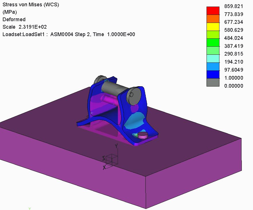
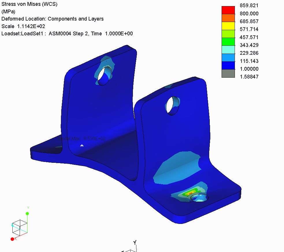
I did a quick test and had success. For the floor and integrated mounting bolts, I made all surfaces part of the original rigid link except for the bottom of the floor where the constraint was applied.
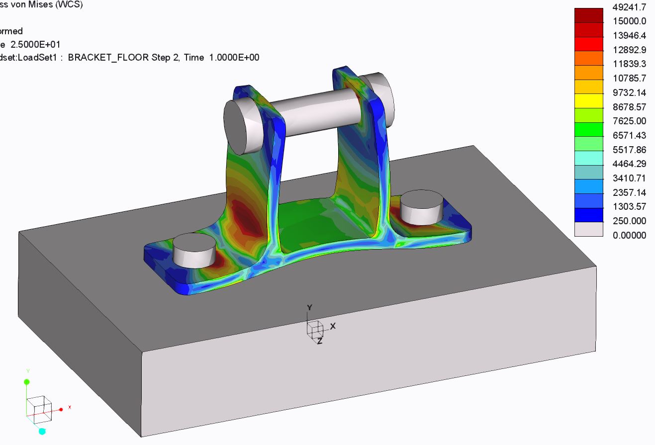
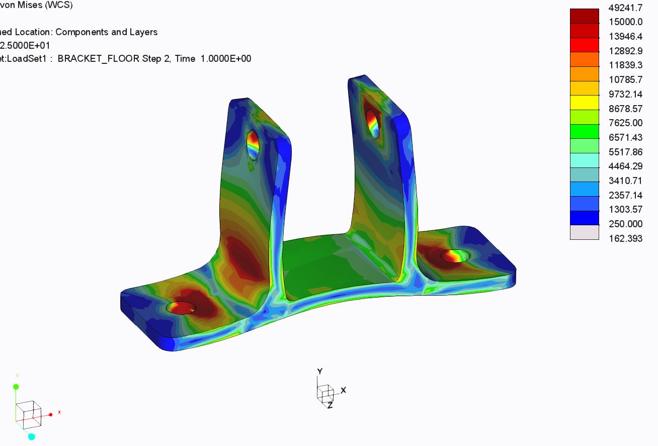
You can see from the image that Creo treats the bolts and floor as infinitely rigid because they have no stress....infinitely rigid = no nodal displacement = no stress. To get the rigid parts to look the way they do below, I set my legend lower limit really small and changed the lower limit color to light gray. For the image of just the bracket, I did as Jonathan suggested and isolated the bracket in the display location tab. Not a real thought out run, just something real quick to show the method.
Jul 31, 2013
07:39 AM
- Mark as New
- Bookmark
- Subscribe
- Mute
- Subscribe to RSS Feed
- Permalink
- Notify Moderator
Please log in to access translation
Jul 31, 2013
07:39 AM
Thanks a lot,
Im using CREO 2 simulate.
So at model setup, I select "free".
Then at the "Refine model" tab, I select "interface" and select the bracket and floor.
I do the same for bracket and horizontal bolt.
If I now run analysis, I have to select "nonlineair/use histories" otherwise Ill end up with lots of errors saying the bolt isnt constrained. I have no experience with nonlineair mode..
There are two steps, 0 at time 0 and step 1 at time 1, which shows results.
I still get two remarks:
" The contact area is non-zero for zero load
factor because there is initial interpenetration
(interference fit) in at least one contact
region or presence of fastener(s) with preload. "
and
" One or more measures were evaluated at (or close to) results singularities.
The values of these measures may be inaccurate, and you must use engineering
judgement when interpreting them. These measures are noted with an asterisk
following the name. "
Thanks sofar!
Jul 31, 2013
03:38 AM
- Mark as New
- Bookmark
- Subscribe
- Mute
- Subscribe to RSS Feed
- Permalink
- Notify Moderator
Please log in to access translation
Jul 31, 2013
03:38 AM
Usually in Mechanica, warnings are just warnings - not errors. You can still continue.
Read them and take note, but then just look at your results critically and decide for yourself whether they're valid.
@Neo: ah, now I understand what you mean by using a rigid link on a component to make it infinitely stiff - neat!
I'm still not sure why the OP wants to make the adjacent parts over-stiff, but there we are...
Jul 31, 2013
12:05 PM
- Mark as New
- Bookmark
- Subscribe
- Mute
- Subscribe to RSS Feed
- Permalink
- Notify Moderator
Please log in to access translation
Jul 31, 2013
12:05 PM
@ OP - Sounds like you opted to create the contact surfaces manually, which is fine. You can also have Creo create them for you, along with measures, etc. by selecting "Detect Contacts" from the pulldown instead of "Interface".
You need to make sure that your parts are "contact" and not free. Originates from what interface you are in. The deafault behavior of Simulate is to go into "bonded" interface (Home --> model setup). Look in the lower left corner of your screen, it should say what mode you are in. In bonded mode all assembly parts that are in contact are considered bonded together unless you otherwise tell Creo that they are free or in contact. So by telling Creo to make them free, they are no longer bonded but also cannot come in contact with each other; hence Creo thinks that the bolt is unconstrained. Long winded explaination just to say that you just need to change the connection to contact if you are in bonded interface.
As for singularities, this can be a result of many things. But in this case, it can be the result of missing a surface on part that you made infinitely stiff.....a change from infinitely stiff to normal in the same part is an infinite jump and will create a singularity...look for stress gradients in parts that should be infitely stiff, there shouldn't be any. Verify the material properties. Sharp re-entrant corners, add a small radius where there is high stress. Your part could be failing, large deformations, etc. Then there are mesh refinements/adjustments but I won't go there for now.
@ Jonathan - From what I've seen, infinitely stiff parts can help to isolate the results when comparing from one software system to another....such as a group effort with multiple users and softwares...more apples to apples. Academic in nature....like a classroom/presentation setting, collaboration, exercise, or contest. That's my guess anyhow.
Aug 01, 2013
12:46 PM
- Mark as New
- Bookmark
- Subscribe
- Mute
- Subscribe to RSS Feed
- Permalink
- Notify Moderator
Please log in to access translation
Aug 01, 2013
12:46 PM
Hm,
I think I've done it all ok, but I cant figure out why I get this warning:
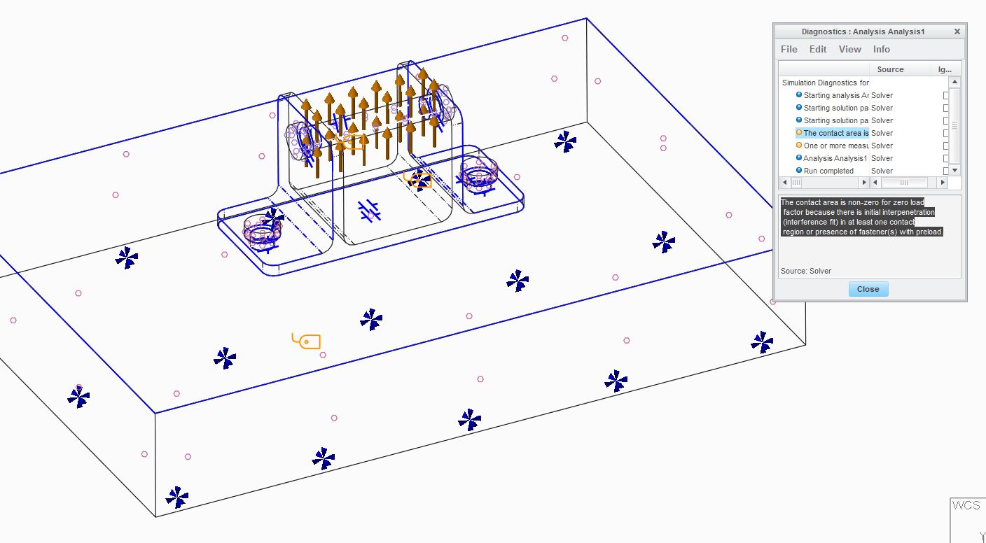
"The contact area is non-zero for zero load
factor because there is initial interpenetration
(interference fit) in at least one contact
region or presence of fastener(s) with preload."
Also theres something funky going on with the horizontal bolt, when Im playing with the deformation scale, see images.
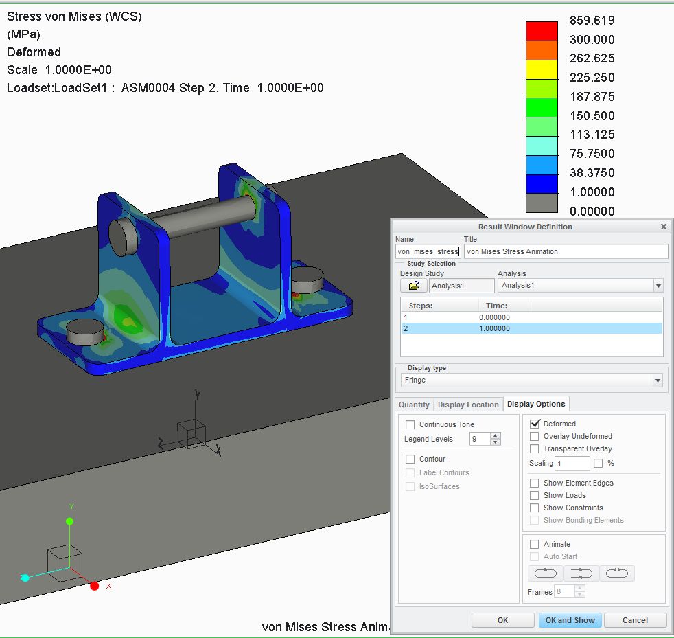
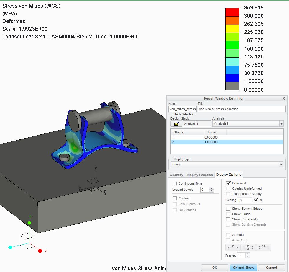
I've attached the original CREO files, perhaps Im still doing something stupid?
I'm also suprised how much effort it takes to set-up a proper simulation!
Cheers!
Aug 01, 2013
12:54 PM
- Mark as New
- Bookmark
- Subscribe
- Mute
- Subscribe to RSS Feed
- Permalink
- Notify Moderator
Please log in to access translation
Aug 01, 2013
12:54 PM
The increase in apparent bolt diameter in your 200x displacement plot suggests that it's rotating - does it have any constraints that would prevent that, or is it free to spin in the holes? To test this you could put a notch or a flat on the head...
Yep, doing FEA to get valid results generally requires some very careful thought at the minimum! Some recent work we did reminded us just how sensitive the results can be to the model set-up - some 'simplified' runs on individual gearbox casing components highlighted certain areas as highly-stressed, yet when we assembled the whole casing these areas showed low stress and different ones looked set to fail.
(Yes, we did that in Mechanica and yes, it was a struggle to get it to run in 24 GB...)
Aug 02, 2013
03:47 AM
- Mark as New
- Bookmark
- Subscribe
- Mute
- Subscribe to RSS Feed
- Permalink
- Notify Moderator
Please log in to access translation
Aug 02, 2013
03:47 AM
@Jonathan: Ive created a notch on the bolt, I dont thinks its rotating.
If I isolate the bracket with the same deformation scale, I dont see an increase in hole diameter, the increased diameter of the bolt is a CREO bug..?
Aug 02, 2013
04:33 AM
- Mark as New
- Bookmark
- Subscribe
- Mute
- Subscribe to RSS Feed
- Permalink
- Notify Moderator
Please log in to access translation
Aug 02, 2013
04:33 AM
What angle was the notch at when you assembled it? I can't see clearly, but it looks like it was at 12 o'clock and now it's closer to 10 o'clock...
Aug 02, 2013
10:43 AM
- Mark as New
- Bookmark
- Subscribe
- Mute
- Subscribe to RSS Feed
- Permalink
- Notify Moderator
Please log in to access translation
Aug 02, 2013
10:43 AM
Thats right,
It rotates, but also grows (the notch itself is also getting bigger, so its not like an envelope of a rotation).
When I constrain the bolt in only the x-direction, the bolt does not grow and the results are almost the same.. 
Aug 02, 2013
12:02 PM
- Mark as New
- Bookmark
- Subscribe
- Mute
- Subscribe to RSS Feed
- Permalink
- Notify Moderator
Please log in to access translation
Aug 02, 2013
12:02 PM
Growing when rotating is perfectly normal when using large scaling, as Jonathan mentioned above. Because of the way that rotations are calculated, they are only valid for small amounts of change. When deformations are scaled, the underlying mathematical assumptions are out of scope...but this is just visual so there is nothing wrong with the actual results because of the scaling. Checking the box for a large deformation should eliminate this effect but may also increase analysis times.
Aug 03, 2013
11:26 AM
- Mark as New
- Bookmark
- Subscribe
- Mute
- Subscribe to RSS Feed
- Permalink
- Notify Moderator
Please log in to access translation
Aug 03, 2013
11:26 AM
Just repeated the analysis in part mode by constraining the hole surfaces and a surface region on top.
I also constrained the clevis outer side walls where the horizontal bolt head and nut would be located.
Used the same material and force.
results assembly mode:
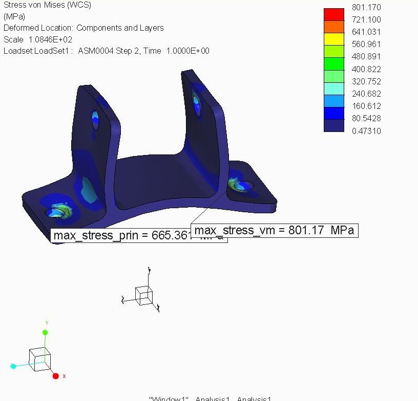
part mode results:
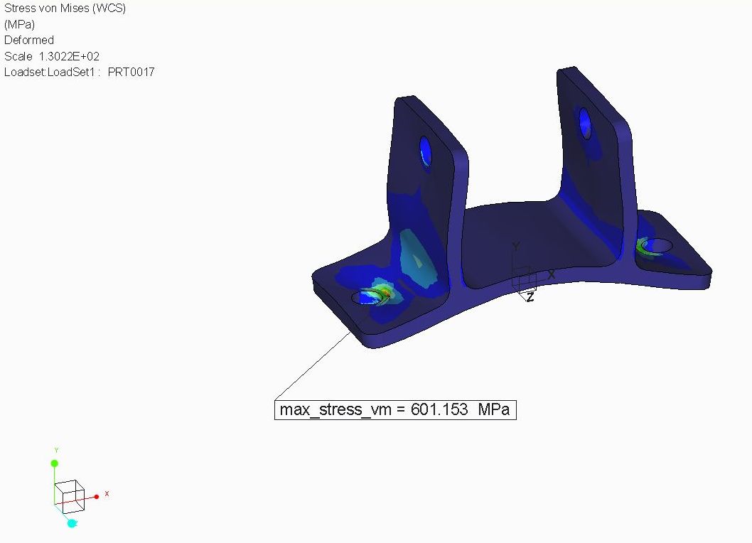
So the .asm result presents about 30% higher stress. I think the .asm setup is closer to the real world.
And part mode really isnt a good idea to get reliable results in cases like these?
Or is this the time to exclude the area around the bolt, to exclude this "peek" stress from the analysis? I dont think in the real world the bracket will actually fail because of too much stress under a bolt-head..
Aug 03, 2013
11:34 AM
- Mark as New
- Bookmark
- Subscribe
- Mute
- Subscribe to RSS Feed
- Permalink
- Notify Moderator
Please log in to access translation
Aug 03, 2013
11:34 AM
I also did an analysis in part mode with excluded elements where the bracket is bolted to the floor and the same in assembly mode. The assembly mode still gives 20% higher stress (max stress both located at the horizontal holes), adding to my assumption that assembly mode is required for this analysis, as the presence of a "floor" appearantly influences stress troughout the bracket.
Any comments on that?
Aug 05, 2013
12:16 AM
- Mark as New
- Bookmark
- Subscribe
- Mute
- Subscribe to RSS Feed
- Permalink
- Notify Moderator
Please log in to access translation
Aug 05, 2013
12:16 AM
Constraining an entire surface makes it stiffer than it would be otherwise. And, as was mentioned above, there's no way to model the interaction with the surface other than creating that interaction in an assembly. If you are getting a singularity, you determine the solution is not converging (p-loop pass, max element order, etc.), and you don't care about the stresses in those areas, then you can can tell autogem to ignore the stresses in those areas for the purpose of convergence...try some mesh refinement by hand in the area first though.
A contact analysis will be more accurate than just constraining surfaces to represent interaction with other components. Making the bolts infinitely stiff is a slight deviation from accuracy to the real world. You can improve on that if you can change the bracket material from linear elastic to at least elasto-plastic. Furthermore, creating a radius on the bolt where it interfaces with the part may help a little...don't reduce the contact diameter though. You could also look at constraining the part in a different way such as fastener features or weighted links, etc. I'd like to hear if anyone has had success with another method.
Ultimately it comes down to engineering judgement and what you deem is important. Your definition of a failing part may be different than others. Bearing failure is common and a reason for spontaneous bolt losening, corrosion, etc. But that may not necessarily deem it a failure in your application. On the analysis side, it helps to get a second opinion either with a hand calculations, another anaylsis from a different approach, or validation through actual testing.


