
Turn on suggestions
Auto-suggest helps you quickly narrow down your search results by suggesting possible matches as you type.
Showing results for
Please log in to access translation
Turn on suggestions
Auto-suggest helps you quickly narrow down your search results by suggesting possible matches as you type.
Showing results for
Community Tip - You can subscribe to a forum, label or individual post and receive email notifications when someone posts a new topic or reply. Learn more! X
- Community
- Creo+ and Creo Parametric
- 3D Part & Assembly Design
- Re: how to create tension beams (steel cable) in s...
Translate the entire conversation x
Please log in to access translation
Options
- Subscribe to RSS Feed
- Mark Topic as New
- Mark Topic as Read
- Float this Topic for Current User
- Bookmark
- Subscribe
- Mute
- Printer Friendly Page
how to create tension beams (steel cable) in simulate
Mar 05, 2017
08:26 AM
- Mark as New
- Bookmark
- Subscribe
- Mute
- Subscribe to RSS Feed
- Permalink
- Notify Moderator
Please log in to access translation
Mar 05, 2017
08:26 AM
how to create tension beams (steel cable) in simulate
Hallo Creo Simulate community
I am working on a frame construction and would like to do some mechanical simulations with this frame. The simple construction is a 3D Frame with cable elements (can only carry tension).
Can anybody help me? How one has to define a "tension only beam" in Creo Simulate?
Thank you for your support
Otto
Labels:
- Labels:
-
Routed Syst. Design
10 REPLIES 10
Mar 06, 2017
09:27 AM
- Mark as New
- Bookmark
- Subscribe
- Mute
- Subscribe to RSS Feed
- Permalink
- Notify Moderator
Please log in to access translation
Mar 06, 2017
09:27 AM
Hello Otto,.
Do you have a plan or an image join us?
Kind regards.
Denis
Mar 06, 2017
11:11 AM
- Mark as New
- Bookmark
- Subscribe
- Mute
- Subscribe to RSS Feed
- Permalink
- Notify Moderator
Please log in to access translation
Mar 06, 2017
11:11 AM
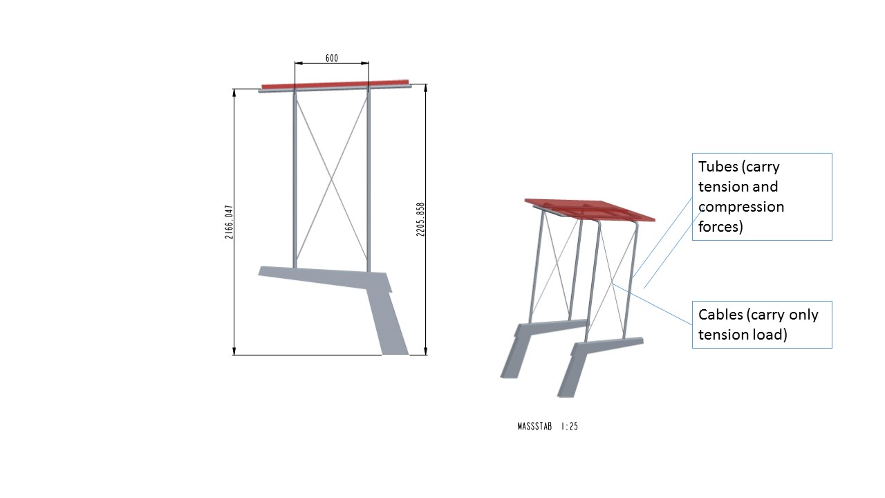
...especially it is a frame construction for a photovoltaic cell. The construction itself is not so important  . It is learning stuff...
But with designes like this I am learning to handle Creo Simulate.
Mainly it is a frame made of tubes (33 mm outer diameter and a wall thickness of 2 mm). To improve the stability I added some robes (cables) to avoid a collapse.
BR otto
Mar 06, 2017
12:18 PM
- Mark as New
- Bookmark
- Subscribe
- Mute
- Subscribe to RSS Feed
- Permalink
- Notify Moderator
Please log in to access translation
Mar 06, 2017
12:18 PM
Can you provide some specifics on what type of analysis you want to do and the goals of it? Generally speaking, Simulate does not have a "tension only beam". However, depending on the conditions of the analysis, you might be able to use a pre-loaded beam element (which will work with any linear analysis) or a deflection-dependent spring element (which will only work in a non-linear analysis).
Mar 06, 2017
02:15 PM
- Mark as New
- Bookmark
- Subscribe
- Mute
- Subscribe to RSS Feed
- Permalink
- Notify Moderator
Please log in to access translation
Mar 06, 2017
02:15 PM
...currently I am designing a 3D frame for a photovoltaic cell which should be mountet on a sailing boot (private stuff). During the design interations I had the idea to start some beam FEA studies to see the stability of the design and to learn how to use Creo Simulate.
The current design of the frame has cables to increase the stability (cables are used to have less welding conections as well as a nice appearance).
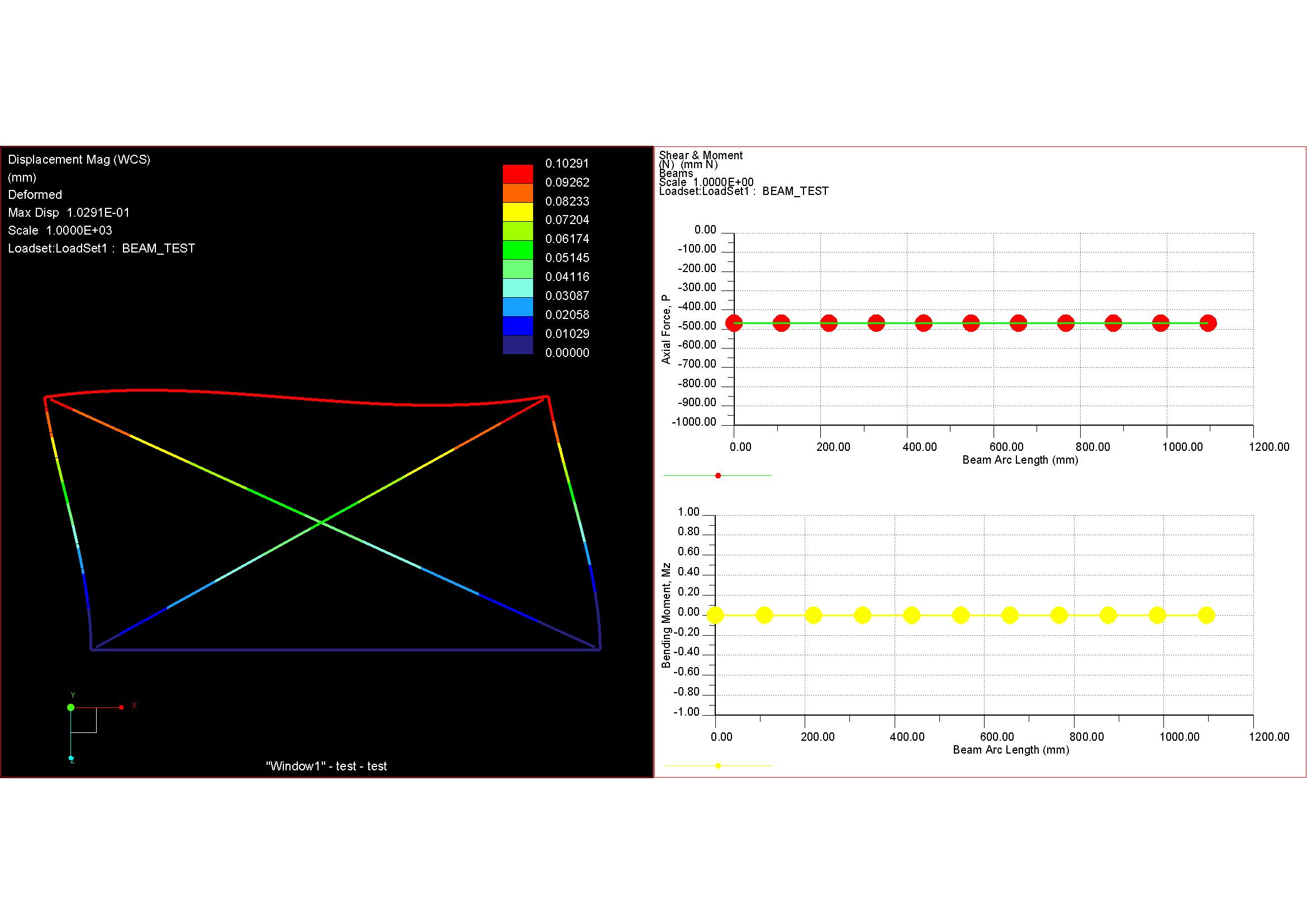
Aim of the simulation is to assess the forces and mechanical loads on the tubes and cables as well as the see the deformation of the frame under load. To be honest it is not really critical but I started and now I would like to finish this task and learn....
thank you otto
Mar 08, 2017
09:29 AM
- Mark as New
- Bookmark
- Subscribe
- Mute
- Subscribe to RSS Feed
- Permalink
- Notify Moderator
Please log in to access translation
Mar 09, 2017
03:06 AM
- Mark as New
- Bookmark
- Subscribe
- Mute
- Subscribe to RSS Feed
- Permalink
- Notify Moderator
Please log in to access translation
Mar 09, 2017
03:06 AM
regards
paul
Mar 09, 2017
03:22 AM
- Mark as New
- Bookmark
- Subscribe
- Mute
- Subscribe to RSS Feed
- Permalink
- Notify Moderator
Please log in to access translation
Mar 10, 2017
03:49 AM
- Mark as New
- Bookmark
- Subscribe
- Mute
- Subscribe to RSS Feed
- Permalink
- Notify Moderator
Please log in to access translation
Mar 10, 2017
03:49 AM
Hi Paul.
Why did you create a rigid link between Beam1 and Beam2 (and also Beam1 and Beam3)?
Why not just simply connect the beams together? See the picture below.
I tested it without Rigid link and the results are pretty much the same.
Regards,
Domen
Mar 10, 2017
04:20 AM
- Mark as New
- Bookmark
- Subscribe
- Mute
- Subscribe to RSS Feed
- Permalink
- Notify Moderator
Please log in to access translation
Mar 27, 2017
05:48 AM
- Mark as New
- Bookmark
- Subscribe
- Mute
- Subscribe to RSS Feed
- Permalink
- Notify Moderator
Please log in to access translation


