Community Tip - When posting, your subject should be specific and summarize your question. Here are some additional tips on asking a great question. X
- Community
- Creo+ and Creo Parametric
- 3D Part & Assembly Design
- Re: "rolling" a sheet in Creo
- Subscribe to RSS Feed
- Mark Topic as New
- Mark Topic as Read
- Float this Topic for Current User
- Bookmark
- Subscribe
- Mute
- Printer Friendly Page
"rolling" a sheet in Creo
- Mark as New
- Bookmark
- Subscribe
- Mute
- Subscribe to RSS Feed
- Permalink
- Notify Moderator
"rolling" a sheet in Creo
Hi there,
I've been a Creo Parametric user for around a year now and I've run into a problem that's stumped everyone around me...
I'm designing a sheet that will be rolled up into a cylinder. This sheet has irregular markings on the top and bottom edges, and I need to see how they line up when this sheet is rolled up into a cylinder. I have the sheet ready, but I cannot figure out how to "roll" it up virtually. Is this even possible?
Thanks in advance!
- Mark as New
- Bookmark
- Subscribe
- Mute
- Subscribe to RSS Feed
- Permalink
- Notify Moderator
It looks quite convincing and quite close to what I need.
However, just to let the purpose of this endeavor be clear... I am trying to bend this model so that I will be able to get a decent estimate of how much material will be left covering the lid/cap after this crimp.
Do you think that this method will be capable of showing me that?
- Mark as New
- Bookmark
- Subscribe
- Mute
- Subscribe to RSS Feed
- Permalink
- Notify Moderator
![]() Sorry I answered the other email before I saw this one. Okay so the bent tab is perfect and the rolled edge is close.
Sorry I answered the other email before I saw this one. Okay so the bent tab is perfect and the rolled edge is close.
To answer your question, yes I think we can show what you're after. The crimp starts as a straight length. I record the length of this bit of straight section before the "crimp". The crimp geometry itself is constrained to be EXACTLY the same length as the straight section. In fact if you vary the angle or any other bits of the crimp geometry, it will resize itself to keep the crimped length equal to the original straight length.
We can vary this, too. If you want to estimate that the crimp itself eats up 20% of the straight length, we can add that. I guess I'm not totally clear on what the crimp should look like. You don't happen to have a real picture of it do you? I can bend it, roll it (as in the picture), HEM it like in a true fold, or just sort of mush it down around the cap. The "mush" method won't give you any real-world geometry or data but it will look convincing enough. the other techniques can be made to yield geometry pretty close to real-world.
Thanks!
-Brian
- Mark as New
- Bookmark
- Subscribe
- Mute
- Subscribe to RSS Feed
- Permalink
- Notify Moderator
Hi there,
Unfortunately, I do not have an actual picture of the design I need... It basically is the same thing. We are forcing the metal onto the plastic cap with enough pressure to create an airtight seal.
Whichever method works best to give real-world geometry would be the best in this case.
- Mark as New
- Bookmark
- Subscribe
- Mute
- Subscribe to RSS Feed
- Permalink
- Notify Moderator

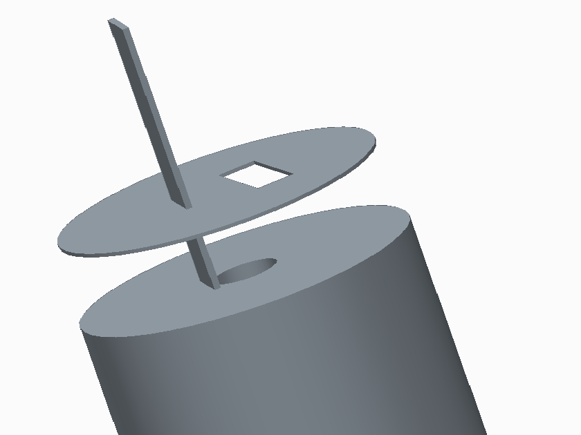
This is my second problem. The vertical tab is not supposed to go through the thin disk. The tab is supposed to bend underneath, fit through the rectangular slot, and the bend over to the right and lay flat on top of the disk.
I'm sure this all too familiar to you, given your previous experience. ^^
- Mark as New
- Bookmark
- Subscribe
- Mute
- Subscribe to RSS Feed
- Permalink
- Notify Moderator
Hi again Pum...
And yes this one I would definitely use the Spinal Bend feature on. You can make those bends really easily and keep the geometry realistic. I'm starting to lose my grip on reality... too many questions in the queue today! ![]()
I'll try to bundle this example with the crimped lip example... unless another one of these modeling gurus wants to make a quickie demo.
Thanks!
-Brian
- Mark as New
- Bookmark
- Subscribe
- Mute
- Subscribe to RSS Feed
- Permalink
- Notify Moderator
Hi Pum... (again)...
Now we're moving on to the bent tab. Again, the solution to this problem seemed like a no-brainer. If you have a 1.00" long tab and you need to bend it, you can easily do this with a spinal bend. You simply need to make sure the "spine" you use for this feature is the same length (1.00" for example) as your tab otherwise stretching or compression can occur.
I started with a simple cylinder again with a straight tab sticking up... similar to what you displayed in your post. I made a small disc-shaped cap with a notch like you showed. Finally, I created a simple curve with the desired bends as you described in your message. I applied the spinal bend and the tab bent itself perfectly... and the rest of the cylinder disappeared.
It occurred to me that the Spinal Bend feature has always been a little squirrelly. There's no reason it should have removed the rest of the model and left ONLY the tab... yet it did. Slowly I recalled that it's always done weird stuff like this.
There were other options for bending this tab. The Warp Bend tool would have absolutely worked. But all of the Warp Tools are really more like playing with virtual clay or putty. There's some parametric dimensions you can apply but these are mostly free-form tools. You'd want something more concrete... so I went back to the Spinal Bend.
The Spinal Bend feature can bend both solids and quilts/surfaces. Because the feature was causing problems when I tried to bend the solid geometry, I decided to use the surface option instead. I made the long tab a surface instead of a solid. I applied the Spinal Bend to the surface using the sketched "spine" I created. The tab bent perfectly... but it left the original surface there, too.
When you bend a solid, the solid just bends. When you bend a surface, the original stays put AND you see a new surface in the bent shape, too. Yet another hassle! Once I had both the bent and unbent tabs, I used the Solidify option to turn them both into solid geometry.
The model can now be tabled to show either the "before bend" or "after bend" version. Likewise, it can be used in an upstream assembly as a flexible component. This would allow you to show the tab in both positions for drawing or documentation purposes.
Again, here are some images of the before and after. Let me know if this seems like what you're after. If so, I'll make a few slides to document the steps. They're pretty easy. I hope this is in the ballpark... click the views below for a larger view.
Let me know if I'm on the right track!
Thanks!
-Brian
- Mark as New
- Bookmark
- Subscribe
- Mute
- Subscribe to RSS Feed
- Permalink
- Notify Moderator
Hi Brian,
Yes, that is almost exactly what I need. It looks so beautiful! I would greatly appreciate any documentation of the steps you went through to achieve this...
- Mark as New
- Bookmark
- Subscribe
- Mute
- Subscribe to RSS Feed
- Permalink
- Notify Moderator
Does that go for the rolled/folded edge AND the bent tab... or just the tab? There are two really (reaaaallly) long posts there. One addresses each topic. Plus I still owe you a tutorial for the "jelly roll".
But hey, I have a good bit of time tonight so I can certainly finish the documentation you need.
Thanks!
-Brian
- Mark as New
- Bookmark
- Subscribe
- Mute
- Subscribe to RSS Feed
- Permalink
- Notify Moderator
In this case, I very much believe family tables are your new best friend. While you can't just drag things around like you want (that would be a great enhancement...), you can create instances to do what you want.
- Mark as New
- Bookmark
- Subscribe
- Mute
- Subscribe to RSS Feed
- Permalink
- Notify Moderator
Hi, thanks for the reply!
I did think of family trees, but I feel that would involve so many different variations. It would involve at least 4 or 5 bends, all of which could be highly variable.... Perhaps I'm missing something here?
- Mark as New
- Bookmark
- Subscribe
- Mute
- Subscribe to RSS Feed
- Permalink
- Notify Moderator
英语不太好不是很懂什么意思,惭愧。。
- Mark as New
- Bookmark
- Subscribe
- Mute
- Subscribe to RSS Feed
- Permalink
- Notify Moderator
Pum/Everyone else...
Okay so FINALLY we're going to dig into this entire battery project and try to make some headway on documentation.
This thread jumps around so much I didn't know where to put this. I'm just going to drop it here and then, hopefully, pull everything together into one document.
FYI... I'm going to take all of the slides I've done for all the questions I've answered on Planet PTC and post them as documents. I'm also going to link them to my own private website which is launching in the next few weeks. But more on that later...
Pum's original question was:
Pum Sang Cho wrote:
I'm designing a sheet that will be rolled up into a cylinder. This sheet has irregular markings on the top and bottom edges, and I need to see how they line up when this sheet is rolled up into a cylinder. I have the sheet ready, but I cannot figure out how to "roll" it up virtually. Is this even possible?
The short answer here is: Yes, well, sort of... it depends! I have gotten as far as I can go... with is 98% of the way to a solution. Hopefully once I post this, the community at large can come together and get us the last 2% of the way there.
The longer and thinner your sheet is, the harder it will be to roll it up into a cylinder. You're going to eventually hit an accuracy wall where Pro/E just can't go any further. Therefore, the first step is to perform a maneuver I've never had to do in almost 25 years of practical Pro/ENGINEER experience... RESET the lower accuracy boundary.
I'd love to get a show of hands to see how many people even knew that was possible!
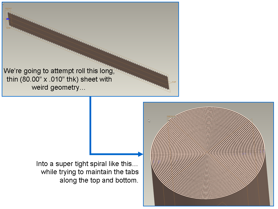
In fact, in addition to resetting the lower accuracy boundary, we need to set several other rarely used switches before I can even begin this tutorial. We're going to be making something that looks like the image below... and it's pretty intensive and nasty although it looks deceptively simple.

... <More steps on the way... I'll edit to add more to this message>
- Mark as New
- Bookmark
- Subscribe
- Mute
- Subscribe to RSS Feed
- Permalink
- Notify Moderator
Thanks Brian!
I look forward to the rest of your writeup. You seem like a very detailed and meticulous person.
- Mark as New
- Bookmark
- Subscribe
- Mute
- Subscribe to RSS Feed
- Permalink
- Notify Moderator
Hi Pum...
I'm totally agonizing over this thing... it feels like I'm giving birth or something. It'll either be great... or totally useless. Sometimes I'm not sure which it's going to be until it's done.
I'm still working. I'm anxious to unveil this presentation because it represents much more than just an answer to your question. It's a bit of a glimpse into my future. Hopefully it isn't junk! ![]()
And I really apologize for the long delay. Maybe if I wasn't taking excruciating detours to worry about fonts, templates, graphics quality, writing 'tone', instructional clarity, and other nonsense... I'd be able to finish faster!
I should be able to post the first of the three tutorial objectives tomorrow morning. I'm going to sleep and get back to it early in the a.m. I'm not answering any more questions on Planet PTC until I clear out the backlog of responses, models, and tutorials I've already promised people. And you're up first!
Take care...
-Brian
- Mark as New
- Bookmark
- Subscribe
- Mute
- Subscribe to RSS Feed
- Permalink
- Notify Moderator
Awesome that you're helping him with this Brian, 2 thumbs up to you! Looking forward to the end result.
- Mark as New
- Bookmark
- Subscribe
- Mute
- Subscribe to RSS Feed
- Permalink
- Notify Moderator
Nice going, Brian and all.
I am curious if the "irregular markings" on the flat sheet will ever line up the way Pum wants. Both in real environment and Pro/E / Creo.
And most importantly I am curious if it will ever turn out as Pro/E / Creo will vitually show it. This is some tough part to make.
- Mark as New
- Bookmark
- Subscribe
- Mute
- Subscribe to RSS Feed
- Permalink
- Notify Moderator
You know Jakub (or Jacob to us Americans ![]() ), that's an excellent point about "lining" up: they won't unless the flat pattern takes into account the constantly decreasing radius, and thus, the changing linear distance. PERHAPS it would be best to put the notches only in the flat pattern part, wrap the foils, and then modify the surface geometry (via a trim) or solid geometry with a radial pattern cut, either at the part level or assembly.
), that's an excellent point about "lining" up: they won't unless the flat pattern takes into account the constantly decreasing radius, and thus, the changing linear distance. PERHAPS it would be best to put the notches only in the flat pattern part, wrap the foils, and then modify the surface geometry (via a trim) or solid geometry with a radial pattern cut, either at the part level or assembly.
A part this complicated, it's hard to diagnose the best approach without seeing what the final geometry SHOULD look like.
Pum, can you please post digital photos of the real finished part if your legal dept. will let you? Thanks.
- Mark as New
- Bookmark
- Subscribe
- Mute
- Subscribe to RSS Feed
- Permalink
- Notify Moderator
Hi Frank,
I really wish I could (I think it would have helped Brian a LOT), but my workplace is very strict about photographs...
- Mark as New
- Bookmark
- Subscribe
- Mute
- Subscribe to RSS Feed
- Permalink
- Notify Moderator
Okay here's part 1... of 3! This was the hardest part though. The other sections won't be as bad. As I said, this one was like giving birth. Remember to click the slides to see them in a larger, more easy-to-read view.
Whew... like I said... part 1.
Thoughts? Comments? Criticisms? Don't be shy, I can take it. I'd rather KNOW if something wasn't good than proceed on the notion that it is and wind up looking silly. ![]()
Thanks guys! More to come...
-Brian
PS: If anyone noticed, yes, slide #1 is missing. I kinda chickened out on including it. I'll explain later- maybe. ![]()
- Mark as New
- Bookmark
- Subscribe
- Mute
- Subscribe to RSS Feed
- Permalink
- Notify Moderator
Hmm... anyone think I may have gone overboard on that one?
- Mark as New
- Bookmark
- Subscribe
- Mute
- Subscribe to RSS Feed
- Permalink
- Notify Moderator
Hi
when you complete all the parts of the tutotial; Please make it a separate document
Searching useful content with different Topic is difficult to find for users in future
Regards
K.Mahanta
- Mark as New
- Bookmark
- Subscribe
- Mute
- Subscribe to RSS Feed
- Permalink
- Notify Moderator
AWESOME writeup Brian! I'm gonna look at the model when I get some time. Been really sick lately......
At least the Football was good this weekend! ![]()
- Mark as New
- Bookmark
- Subscribe
- Mute
- Subscribe to RSS Feed
- Permalink
- Notify Moderator
Really overwhelming amount of info, Brian.
![]()
And nicely done!
- Mark as New
- Bookmark
- Subscribe
- Mute
- Subscribe to RSS Feed
- Permalink
- Notify Moderator
Wow Brian,
That is an AMAZING writeup. Textbook-quality material. Thank you so much...
- Mark as New
- Bookmark
- Subscribe
- Mute
- Subscribe to RSS Feed
- Permalink
- Notify Moderator
what amazed me is your computer config....i tried a 5 turn's spiral and then create a sweep wall in sheet metal...it got hang....i have 1 gb nvidia graphic card 4 gb ram...:(
- Mark as New
- Bookmark
- Subscribe
- Mute
- Subscribe to RSS Feed
- Permalink
- Notify Moderator
Brian - I'm extremely lucky to come across this thread as I am trying to acheive something simular to this. Although I keep getting stuck at step #4 because my geometries intersect ![]()
Anyhow I have manage to create a simple method to create a tightly rolled cylinder.....
1 - Simply create a datum curve with a cylindical equation. set the IR to something like 5mm and OR to 50mm, and set number of layers to 20. This will give you a tight spiral......
2 - Next select INSERT > SWEEP > PROTRUSION
3 - Now sketch a long thin rectangle i.e. 100mm x 0.5mm....now tick 'finish and there you go!!
SEE IMAGE ATTACHED
The only addtion to this which I cannot achieve is the zig-zag pattern I am trying to create which will follow the datum curve all the way to the centre. It can be done with thousands of Datum Points, but there must be an easier WAY?!! This is why I started searching for Spinal bend methods as I though it might be do able If i started with a flat sheet with a zig-zag surface already in place....?
- Mark as New
- Bookmark
- Subscribe
- Mute
- Subscribe to RSS Feed
- Permalink
- Notify Moderator
Thanks Alistair...
At the time I wrote it I was making several of these a week for users on PTC Community with plans to save them all on my personal website. But... I got overwhelmed with work and personal issues so I had to scale back my efforts. I'm glad you were able to make use of the information.
I've seen your screenshot and I see what you're trying to do. I agree that an equation to create the spiral is the best way to go. The tutorial used something more complex because the user needed a spiral with all these crazy cuts patterned along the length. In your case, a simple spiral equation works well.
To create the zig-zag, there are several things I would try. First, try patterning along a curve. Use the curve created from the equation to replicate the zig-zag geometry along the entire spiral. You can choose the number of zig-zags or the spacing between them (and let Creo make as many as it can at the given spacing).
If this doesn't work... you might try patterning the zig-zags as enclosed SURFACE features. You will not get any self-intersection errors this way. Once the pattern is created, SOLIDIFY the surfaces to make them solid. This could be dicey and you may need to crank the accuracy down to a smaller value to make it work- but there's a chance this technique will work as long as your spiral isn't really, really tight (like the one in my tutorial).
The last thing you might try would be to make a surface from your spiral equation. Instead of making a solid, make it a surface (like I did in the tutorial). Drop a point on the surface at the very edge... it has to be an "on surface" point but it can lie on the edge. Then, use Flatten Quit to make a flat surface. Next, create your zig-zags using the flat quilt as a reference. Make these solid extrusions. Allow them to extrude down the length of the quilt. Once you've patterned your zig-zag down the length of the surface, use Thicken to give the original surface a thickness and turn it into a solid. Now you'll have a long, thin solid with the zig-zags running down the length of them. Finally, use Solid Bend (renamed Flatten Quilt Deformation in Creo 2) to bend the solid back into it's coiled shape.
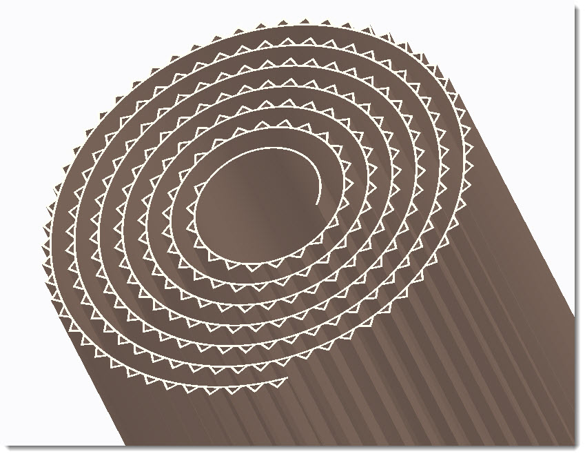
This last technique definitely works. I've tried it (at least in Creo 2)... here's what it looks like:

I realize I put the zig-zags on the wrong side but that should be easy to fix. I've included a model for you to examine. It's been done using Creo 2. I didn't catch which version of Pro/E or Creo you were using. If it's something earlier than 5, let me know.
Thanks!
-Brian
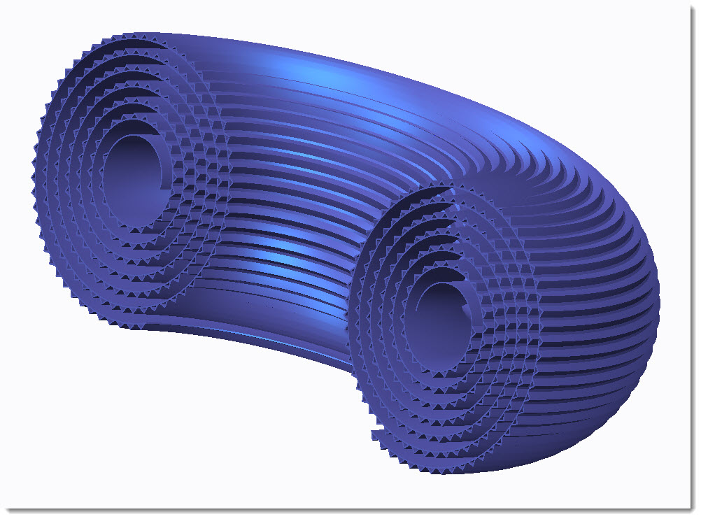
Just for the heck of it... here's an example of something else you can do...

You can use your imagination... it's possible to make some crazy shapes with Creo.
- Mark as New
- Bookmark
- Subscribe
- Mute
- Subscribe to RSS Feed
- Permalink
- Notify Moderator
Hi Brain,
Thanks for taking the time out to answer my question and answer it in such detail. Very Helpful!
I am using Wildfire 2 at work and 4 at home currently, so I dont know how that does effect the methods you have suggested above.
When I get a chance to I will work my way through you advised methods and see if I can get this to work! The examples you have produced look great!
Thanks
Alistair.
- Mark as New
- Bookmark
- Subscribe
- Mute
- Subscribe to RSS Feed
- Permalink
- Notify Moderator
Good luck Alistair...
If you get stuck, let me know. Unfortunately I just removed Wildfire 2 from my workstation so I can't really go back to redo the geometry in WF2. I can help you through the process though if you have specific questions.
Thanks!
-Brian
- Mark as New
- Bookmark
- Subscribe
- Mute
- Subscribe to RSS Feed
- Permalink
- Notify Moderator
Hi,
If one of the responses helped resolve your issue, would you please mark it as the Correct Answer? That way other users visiting the discussion will know; as the correct answer gets copied right below the question.
Thanks,
Amit
- « Previous
-
- 1
- 2
- Next »


