Community Tip - Did you know you can set a signature that will be added to all your posts? Set it here! X
- Community
- Creo+ and Creo Parametric
- 3D Part & Assembly Design
- Re: vessel design, man hole, nozzle
- Subscribe to RSS Feed
- Mark Topic as New
- Mark Topic as Read
- Float this Topic for Current User
- Bookmark
- Subscribe
- Mute
- Printer Friendly Page
vessel design, man hole, nozzle
- Mark as New
- Bookmark
- Subscribe
- Mute
- Subscribe to RSS Feed
- Permalink
- Notify Moderator
vessel design, man hole, nozzle
Dear Folks
How to create in creo elements pro 5.0 by below attached screen shot.
Just assume the dimensions. I have to know which tool can be used to create like this?
Thanks in advance
Viswanathan.K
This thread is inactive and closed by the PTC Community Management Team. If you would like to provide a reply and re-open this thread, please notify the moderator and reference the thread. You may also use "Start a topic" button to ask a new question. Please be sure to include what version of the PTC product you are using so another community member knowledgeable about your version may be able to assist.
- Mark as New
- Bookmark
- Subscribe
- Mute
- Subscribe to RSS Feed
- Permalink
- Notify Moderator
Are you trying to get the flat plate layout of the plate for the tank given the fact that you have the manhole ring in the vessel? If so, I would do an extrude cut in the plate for the weld clearance around the manhole ring in the plate with kerf and bevel as necessary (kerf could come with the extrude, the bevel would be a secondary operation - adding the chamfer). Then flatted the plate out after the the material has been removed. It should be close enought for weldeding the pressure vessel.
As for the vessel design, it depends upon which section of the code required for the build. Is it ASME Section I, IV or VIII? The code is very specific for the the material and design of the vessel and what safety factors are needed in your calculations.
Do you have certified welded for the construction of the vessel. The head of the vessel can most likely be purchased from a certified vendor as well as the nozzles and man holes. The manholes are usually bought in a set. The ring and the cover with it's fasteners.
If this is a none code vessels, then it is up to you basic engineering design for stresses.
Thanks, Dale
- Mark as New
- Bookmark
- Subscribe
- Mute
- Subscribe to RSS Feed
- Permalink
- Notify Moderator
Dear Dale
Actually what am i trying to say is, in creo elements pro, how to merge the vessel surface and man hole, i have extrude the man hole, I am not able to merege both and some distance was there. if i fill the distance i willl get excat like that as above phot.
How to merege the vessel surface and man hole using creo elements pro/5.0 by sheet metal.
Some example screen shot i have created, just view it.
Thanks advance
Viswanathan.K
- Mark as New
- Bookmark
- Subscribe
- Mute
- Subscribe to RSS Feed
- Permalink
- Notify Moderator
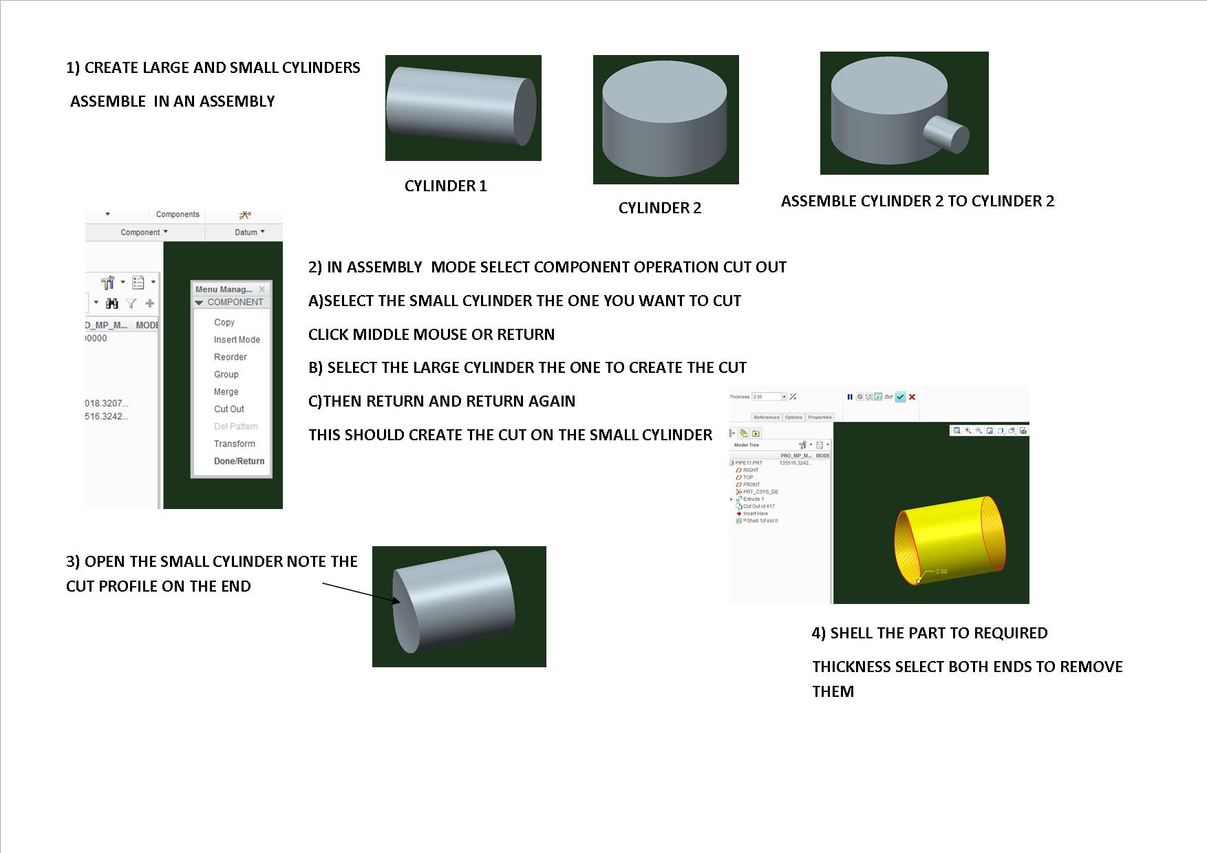
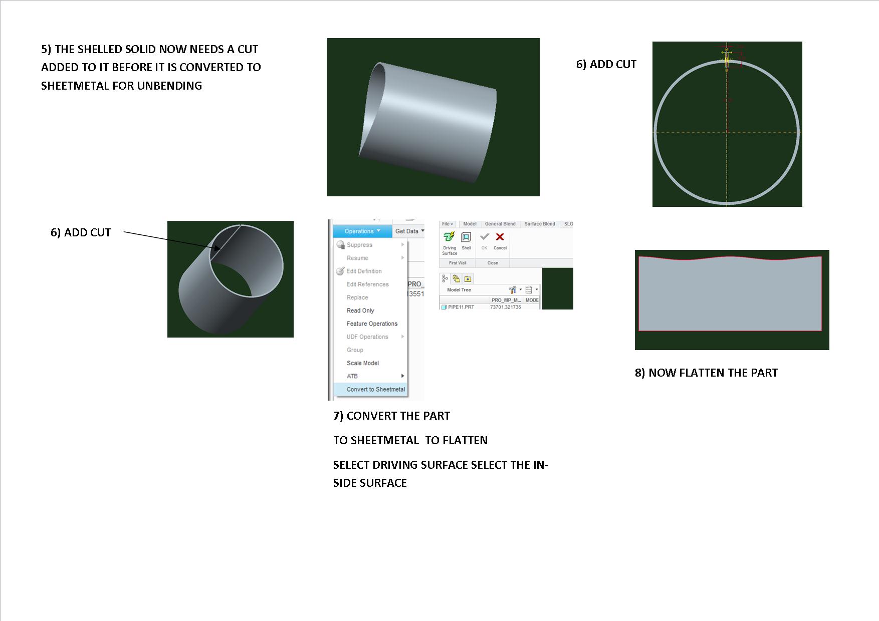
you could create 2 cylinders assemble them in an assembly, then use component operations cut out
cut the large cylinder to from the small one
then convert the solid small cylinder to a sheet metal part using operations convert to sheetmetal and use shell then you could cut a section from the cylinder to allow it to be unfolded i will post a picture with the work flow during my work break
G
- Mark as New
- Bookmark
- Subscribe
- Mute
- Subscribe to RSS Feed
- Permalink
- Notify Moderator
From my experience with pressure vessels, you have an elliptical hole in the vessel wall to receive the manhole ring. The manhole rings typically with protrude through the wall so that you can weld the ring both internally and externally in order to have sufficient weld surface for the related pressure.
Given that, you could use the man hole ring to make an assembly cut into the vessel wall surface. Then afterward you can make an assembly with the vessela and the man hole ring.
If this is just a nozzle, again, most designs allow for the nozzle wall to protrude inside the vessel and are not "matched" cut. I would just design the nozzle and assembly it to the vessel.
Thanks, Dale
- Mark as New
- Bookmark
- Subscribe
- Mute
- Subscribe to RSS Feed
- Permalink
- Notify Moderator
here are some pictures if you want to use the Assembly cut option

- Mark as New
- Bookmark
- Subscribe
- Mute
- Subscribe to RSS Feed
- Permalink
- Notify Moderator

- Mark as New
- Bookmark
- Subscribe
- Mute
- Subscribe to RSS Feed
- Permalink
- Notify Moderator
Isn't it possible to use "extrude to selected"?
Or is this Creo functionality, not in older Pro/E versions?
I'm currently developping a very advanced vessel desiger in Creo + SmartAssembly.
Drawing vessels like this should be 15-20min of work, including most 2D drawings.
- Mark as New
- Bookmark
- Subscribe
- Mute
- Subscribe to RSS Feed
- Permalink
- Notify Moderator
Dear Jeroen
Coud you guide me how to create like advance?
Regards
Viswanathan.K
- Mark as New
- Bookmark
- Subscribe
- Mute
- Subscribe to RSS Feed
- Permalink
- Notify Moderator
Hello,
SmartAssembly is not something that is ready "off the shelf".
It is a blank environment in which you can start programming.
Part of the programming is by creating models in 3D, the other part is writing code.
It's a bit like programming in BASIC or VBA. It is not that hard if you are a bit familiar with programming.
The best way to start with this, is to find somebody (engineering company or PTC supplier with SmartAssembly knowledge).
It is, depending on your requirements, much to very much programming.
But afterwards, you will win much time!
- Mark as New
- Bookmark
- Subscribe
- Mute
- Subscribe to RSS Feed
- Permalink
- Notify Moderator
hi visu
i m also involved with boiler vessels and nozzles (cylinderical, spherical, elipsoidal dishes,etc)
it involves only simple extrude or revolve, no need of assembly
1. make the base vessel by extrude or revolve
2. make a datum plane parallel to the axis of the base vessel at the specific height
3. then with this datum plane as the sketching plane extrude until next or selected(surface) option
you will get a nozzle surface merged with the vessel surface
like this you can cut a dish(for nozzle) from the vessel or make a cut in the base vessel for the recieving nozzle also


