Turn on suggestions
Auto-suggest helps you quickly narrow down your search results by suggesting possible matches as you type.
Showing results for
Please log in to access translation
Turn on suggestions
Auto-suggest helps you quickly narrow down your search results by suggesting possible matches as you type.
Showing results for
Community Tip - Visit the PTCooler (the community lounge) to get to know your fellow community members and check out some of Dale's Friday Humor posts! X
- Community
- Addtl Creo Products (View/Sketch/Illustrate/Layout/ Schematics and Creo Direct)
- Addtl Creo Products (View/Sketch/Illustrate/Layout/ Schematics and Creo Direct)
- Re: Creating a curve between two planes
Translate the entire conversation x
Please log in to access translation
Options
- Subscribe to RSS Feed
- Mark Topic as New
- Mark Topic as Read
- Float this Topic for Current User
- Bookmark
- Subscribe
- Mute
- Printer Friendly Page
Creating a curve between two planes
Feb 07, 2013
02:24 PM
- Mark as New
- Bookmark
- Subscribe
- Mute
- Subscribe to RSS Feed
- Permalink
- Notify Moderator
Please log in to access translation
Feb 07, 2013
02:24 PM
Creating a curve between two planes
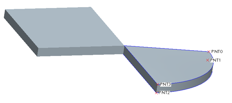
I want to create a revolved surface rotated 90 degrees, the starting point is on one plane and the end point is on another plane. How can I create a revolved surface with the top going between these two points. I've added a picture to try to illustrate what I'm trying to do. This is probably very simple, I just haven't used ProE in a while.
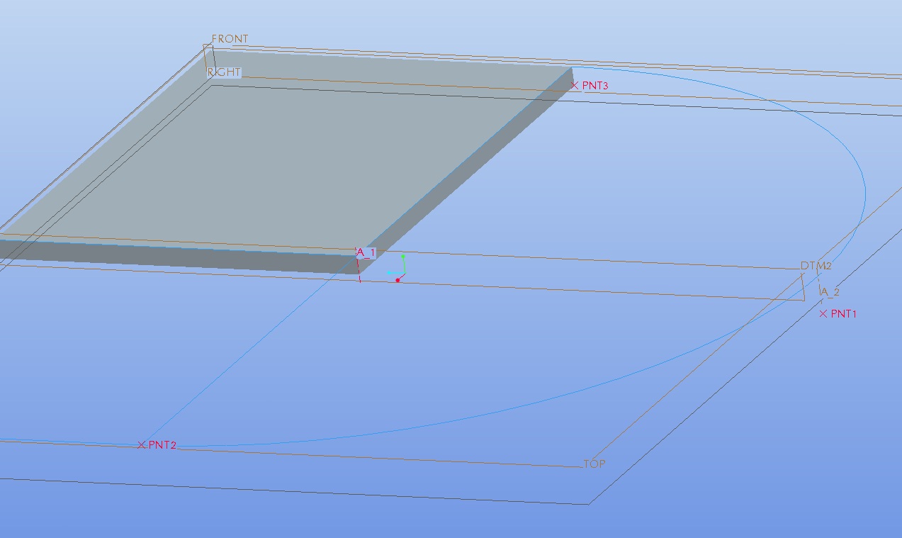
So the axis of rotation is the highlighted axis A1. The points are the two closest points point 1 and 2 I believe. So the revolve will go from the point 2 to point one which is a 12 inch drop while the axis will stay the same.
Labels:
- Labels:
-
Creo Illustrate
19 REPLIES 19
Feb 07, 2013
03:12 PM
- Mark as New
- Bookmark
- Subscribe
- Mute
- Subscribe to RSS Feed
- Permalink
- Notify Moderator
Please log in to access translation
Feb 07, 2013
03:12 PM
I don't know exactly what you are trying to achieve, but hopefully this response will help.
Generally speaking, to create a revolve feature you need two things: A sketch (either internal or external) and an axis. You already have the axis, so you just need the sketch. You mention that you want the revolve to go from point 2, to point 1. Practically speaking, there is no difference in making the revolve go from point 2 to point 1, or to go from point 1 to point 2 (unless design intent dictates otherwise).
Just by looking at the photo, I'm guessing that you will want to make the sketch defining the shape of the feature on the plane DTM2 and select axis A_1 as the revolve axis. Once that is done you can specify that you want the revolve to to travel 90 degrees, or you can click the option to have the revolve stop at a specific point, and select point PNT2.
Is this what you were looking for?
Feb 07, 2013
03:20 PM
- Mark as New
- Bookmark
- Subscribe
- Mute
- Subscribe to RSS Feed
- Permalink
- Notify Moderator
Please log in to access translation
Feb 07, 2013
03:20 PM
No. Let me try to explain better. In this image I've attached I've drawin the cross section I want to revolve. Notice that point 1 is on a lower plane than point 2. A revolve will simple rotate this around the axis. I want to rotate this about that same axis but I want it to also slide up to the top plane. So in addition to revolving I want it to slide upwards...does that help at all?
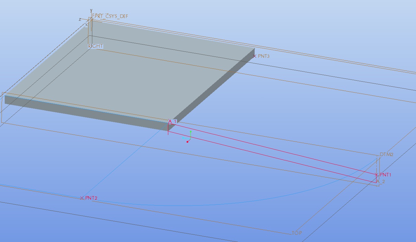
Think of the rotation as a 90 degree section of a helical coil. I want this profile to follow a helical profile.
Feb 07, 2013
03:47 PM
- Mark as New
- Bookmark
- Subscribe
- Mute
- Subscribe to RSS Feed
- Permalink
- Notify Moderator
Please log in to access translation
Feb 07, 2013
03:47 PM
Like I said, helical. So, you want the location on the axis to stay the same, but make the cross section change from a rectangle to a parallellogram?
Like I said, it depends on what end conditions are desired. Should the arc you show be tangent to the plane at both the start and end?
Feb 07, 2013
03:58 PM
- Mark as New
- Bookmark
- Subscribe
- Mute
- Subscribe to RSS Feed
- Permalink
- Notify Moderator
Please log in to access translation
Feb 07, 2013
03:58 PM
I guess I don't understand exactly what you mean by arc being tanget to the plane The arc is the projected profile I want to follow and it is tangent to both start and end point. The cross section shouldn't have to change much but yes I guess it will have to change a little bit in order to follow the helical path.
Feb 07, 2013
04:20 PM
- Mark as New
- Bookmark
- Subscribe
- Mute
- Subscribe to RSS Feed
- Permalink
- Notify Moderator
Please log in to access translation
Feb 07, 2013
04:20 PM
Frank, I have little doubt that you will be able to create the feature but please correct me if I am wrong: I don't see how you can easily create a solid without having a nasty "geometry singularity" at the edge of the part shared with the A_1 axis. It seems to me that you might have to stitch together a few individual surfaces.
Feb 07, 2013
06:27 PM
- Mark as New
- Bookmark
- Subscribe
- Mute
- Subscribe to RSS Feed
- Permalink
- Notify Moderator
Please log in to access translation
Feb 07, 2013
06:27 PM
Oh my God, I've created a Black Hole! 
Is this what you wanted Christian?
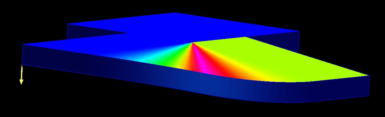
The first method or 2 I tried didn't work. The VSS gave some eird results, so I did a boundary blend. I tried to thicken it, and got some weird distortion, and offsetting the initial surface failed, so made 2 different boundary blends to make sure the thickness stayed correct. I did a surface analysis on it to show the outer edges ARE tangent to the 2 planes, but become less tangent towards the axis. Just in giving it maybe 15 minutes, I can't see how to force it to be tangent at the axis, there's just too much axial displacement. Have fun with it guys.....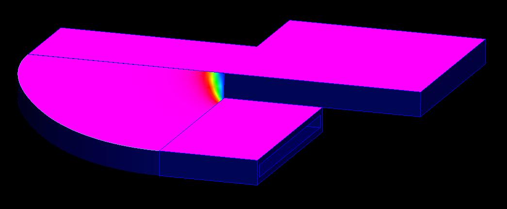
Feb 07, 2013
07:03 PM
- Mark as New
- Bookmark
- Subscribe
- Mute
- Subscribe to RSS Feed
- Permalink
- Notify Moderator
Please log in to access translation
Feb 07, 2013
07:03 PM
I too tried the VSS and got some... interesting results. I ended up making each face with a boundary blend, merging them together, and solidifying the merge. For some reason it feels like cheating going this route, but I'll quickly show my process in case it helps.
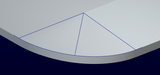
I first made points to create the vertices of the rounded faces.

I then made a wireframe of the solid. Each line you see is an individual datum curve (A total of six datum curves).
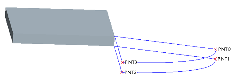
I then made each face individually (a total of five) as a boundary blend feature (so you now have a hollow shell).
I selected each of the individual boundary blends and performed the Merge operation (if you go this route, careful in the order that you select the faces).
I then performed the Solidify operation on the Merge feature I previously created to make make it a solid.
I don't think it's perfect... but it's all I can come up with.
Feb 07, 2013
07:11 PM
- Mark as New
- Bookmark
- Subscribe
- Mute
- Subscribe to RSS Feed
- Permalink
- Notify Moderator
Please log in to access translation
Feb 07, 2013
07:11 PM
Look at the part I attached to my last post.
Feb 07, 2013
07:59 PM
- Mark as New
- Bookmark
- Subscribe
- Mute
- Subscribe to RSS Feed
- Permalink
- Notify Moderator
Please log in to access translation
Feb 07, 2013
07:59 PM
Okay the purple part is interesting. The 6 datum curve example is closest to what I'm trying to do, I'll give that a try. Thanks for all your effort to help me on this everybody!
Feb 07, 2013
08:01 PM
- Mark as New
- Bookmark
- Subscribe
- Mute
- Subscribe to RSS Feed
- Permalink
- Notify Moderator
Please log in to access translation
Feb 07, 2013
08:01 PM
Ahh, ok. I thought tangencies where desired, as well as a full thickness drop in elevation in 90deg.
Good luck!
Feb 07, 2013
09:21 PM
- Mark as New
- Bookmark
- Subscribe
- Mute
- Subscribe to RSS Feed
- Permalink
- Notify Moderator
Please log in to access translation
Feb 07, 2013
09:21 PM
I took Kyle's approach and added tangents to the end of the datum curve. Then used the datum curve with a Boundary Blend to get a nice sweep to the transition. In order to thicken it normal to the flat plane, I copied and transformed a copy of the blend face. Since copy doesn't give you the capped end option, the outside rounded face was swept. Closed up the other two and it solidified beautifully. All the other chunks were simple solid extrudes.

Feb 08, 2013
12:38 PM
- Mark as New
- Bookmark
- Subscribe
- Mute
- Subscribe to RSS Feed
- Permalink
- Notify Moderator
Please log in to access translation
Feb 08, 2013
12:38 PM
I guess I didn't look at the second of Christian's examples. I wanted to extend the tangency condition as far as possible, smoothing the transition.
One thing to think of though, is if you're bending sheetmetal, you will not get a nice sylindrical outer surface, it'll be more elliptical if viewed form the top, because the parallelogram shortens the radius. Also, sheetmetal wouldn't give you a parallelogram anyways, the outer (shown cylindrical) surface would tend to always remain perpendicular to the top surface, twisting as it angled. I modeled both assuming you somehow wanted a perfectly cylindrical surface (because you can't really tell from the pictiure.
This is why, in order to create the correct geometry, you have to take into consideration exactly how it will be made.
Have fun.
Feb 08, 2013
12:58 PM
- Mark as New
- Bookmark
- Subscribe
- Mute
- Subscribe to RSS Feed
- Permalink
- Notify Moderator
Please log in to access translation
Feb 08, 2013
12:58 PM
It is all guesswork until you wrangle the full context about the request.
Feb 08, 2013
01:04 PM
- Mark as New
- Bookmark
- Subscribe
- Mute
- Subscribe to RSS Feed
- Permalink
- Notify Moderator
Please log in to access translation
Feb 08, 2013
01:04 PM
Yup. Hard to help without knowing EXACTLY the geometry needed. But, hopefully we've given him some things to think about. I wish I could open your models, but I'm stuck on WF5/creo.
Feb 08, 2013
01:36 PM
- Mark as New
- Bookmark
- Subscribe
- Mute
- Subscribe to RSS Feed
- Permalink
- Notify Moderator
Please log in to access translation
Feb 08, 2013
01:36 PM
Isn't there an app for that?
...I wish I could open your models, but I'm stuck on WF5/creo.
Feb 08, 2013
01:38 PM
- Mark as New
- Bookmark
- Subscribe
- Mute
- Subscribe to RSS Feed
- Permalink
- Notify Moderator
Please log in to access translation
Feb 08, 2013
01:38 PM
I'm not intentionally trying to beat a dead horse, but some final thoughts on my end:
When I made my model, I controlled the two end points of the curved surface to be tangent to the axis. I neglected to control the geometry of the curve between those two points, thus creating an arc that was not tangent to the axis at all places. At the time I didn't think much of it, but I now consider that to be a significant oversight. The geometry of that curved surface is actually extremely complex in a very subtle way. If it is a critical feature in the part, it might be worth making the curved surface slightly longer in the radial direction and lop this extra material with an extruded cut. This would ensure you have a perfect cylindrical outer shape on the curve. Unfortunately I believe that this would also affect the wave shape of the feature (although probably not by much). Depending on tolerances, you might never know it.
Funny, you would think that this would be a simple feature to make. Right up until you try... I've definitely enjoyed the discussion though!
Feb 08, 2013
01:49 PM
- Mark as New
- Bookmark
- Subscribe
- Mute
- Subscribe to RSS Feed
- Permalink
- Notify Moderator
Please log in to access translation
Feb 08, 2013
01:49 PM
I think Frank came closest with his latest entry by wrapping a sketch onto a cylindrical face. Funny thing is, Creo wouldn't allow tangency in the boundary blend on the ending where it did on the beginning. However, it is tangent by definition so it shouldn't matter.
I also forgot that merge would trim at the same time. And I learned you can make mass properties a feature and optionally place it in the footer. Thanks Frank!
Feb 08, 2013
03:10 PM
- Mark as New
- Bookmark
- Subscribe
- Mute
- Subscribe to RSS Feed
- Permalink
- Notify Moderator
Please log in to access translation
Feb 08, 2013
03:10 PM
Yeah, sometimes you cannot force tangencies on all boundaries, like you think you SHOULD be able to. sometimes I think it's a rounding error on Pro/E's part. I used an equation using pi in the section for the wrap, to make the length of the curve correct. If I'd made the cyclinder actually elliptical, as I mentioned, it would have changed that. You make which ones you can tangent, and leave the others free. I'd say even the end was tangent to XXXX places, the analysis seemed to think so.
You might also want to look at the rules for the layers. Though it's a little buggy (sometimes things that should go on a layer don't), the nice thing about them is that you can "extend" the rules from an assembly down through all the parts in it, sub-assemblies and all. I use it to fix old models, models made by other company, and imported models.
Happy to help. Glad to be able to have a little geometry fun now and then. I LOVE using wraps!
Feb 07, 2013
03:15 PM
- Mark as New
- Bookmark
- Subscribe
- Mute
- Subscribe to RSS Feed
- Permalink
- Notify Moderator
Please log in to access translation
Feb 07, 2013
03:15 PM
I THINK he wants a helical feature. Depends on the geometry you really want. What should the ends look like? It's an ambiguous question.