Turn on suggestions
Auto-suggest helps you quickly narrow down your search results by suggesting possible matches as you type.
Showing results for
Please log in to access translation
Turn on suggestions
Auto-suggest helps you quickly narrow down your search results by suggesting possible matches as you type.
Showing results for
Community Tip - Did you get an answer that solved your problem? Please mark it as an Accepted Solution so others with the same problem can find the answer easily. X
- Community
- Addtl Creo Products (View/Sketch/Illustrate/Layout/ Schematics and Creo Direct)
- Addtl Creo Products (View/Sketch/Illustrate/Layout/ Schematics and Creo Direct)
- Help need with odd Chamfer /Pocket feature
Translate the entire conversation x
Please log in to access translation
Options
- Subscribe to RSS Feed
- Mark Topic as New
- Mark Topic as Read
- Float this Topic for Current User
- Bookmark
- Subscribe
- Mute
- Printer Friendly Page
Help need with odd Chamfer /Pocket feature
Dec 17, 2012
07:58 AM
- Mark as New
- Bookmark
- Subscribe
- Mute
- Subscribe to RSS Feed
- Permalink
- Notify Moderator
Please log in to access translation
Dec 17, 2012
07:58 AM
Help need with odd Chamfer /Pocket feature
Hi,
I having problem creating this feature I have attached some pictures to help illustrate what I am trying to achieve.
I have started with a Chamfer tool with the following settings:
45xD
Set Chain 1 – Standard selected 3 sides,
I have also tried Rule based and selecting Partial loop but the model fails to generate when I exiting the sketch.
Hope you can help with some pointers please as I am new to proE coming from a SW background. Thanks in advance for your help.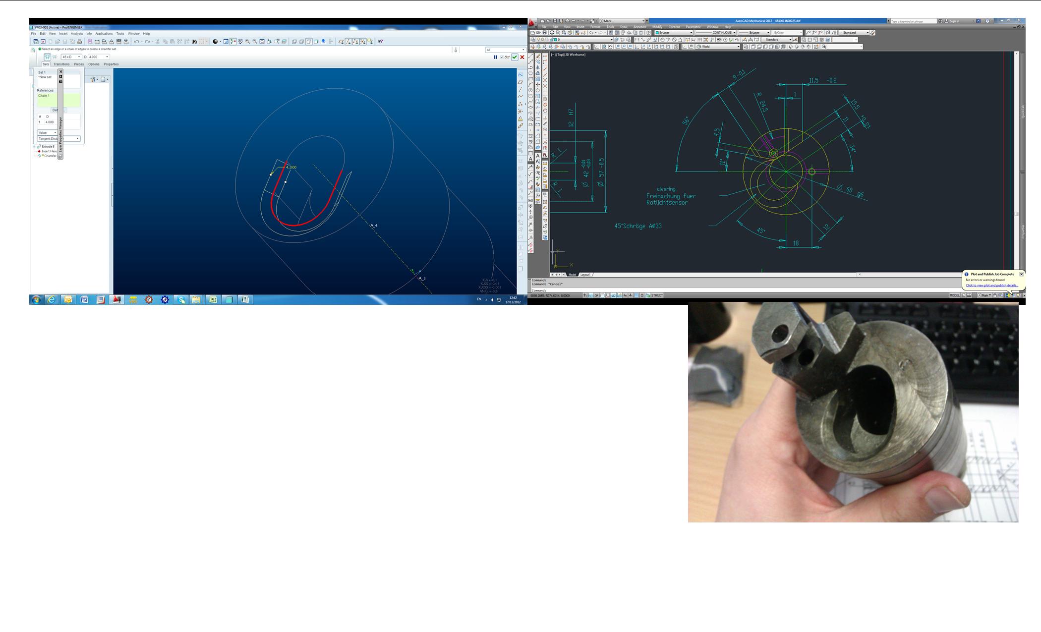
Solved! Go to Solution.
Labels:
- Labels:
-
Creo Illustrate
ACCEPTED SOLUTION
Accepted Solutions
Dec 18, 2012
08:22 AM
- Mark as New
- Bookmark
- Subscribe
- Mute
- Subscribe to RSS Feed
- Permalink
- Notify Moderator
Please log in to access translation
10 REPLIES 10
Dec 17, 2012
08:15 AM
- Mark as New
- Bookmark
- Subscribe
- Mute
- Subscribe to RSS Feed
- Permalink
- Notify Moderator
Please log in to access translation
Dec 17, 2012
08:15 AM
Hi Mark,
Looks like a candidate for a Sweep to me (in WF4 it would be a Variable Section Sweep with the option "Constant Section" selected... not sure what that's become in Creo).
Sketch your cutter path, then create a Sweep and select the path, then sketch the section within the Sweep - it should just be a triangle.
HTH!
Dec 17, 2012
02:32 PM
- Mark as New
- Bookmark
- Subscribe
- Mute
- Subscribe to RSS Feed
- Permalink
- Notify Moderator
Please log in to access translation
Dec 17, 2012
02:32 PM
Yep, this is a great place to use sweep. It will let you control your intended tool path as well.
If you insist on using the chamfer, however, you will need to make the recess to the shape of the tool-path and then add the through hole after the chamfer.
Dec 18, 2012
06:14 AM
- Mark as New
- Bookmark
- Subscribe
- Mute
- Subscribe to RSS Feed
- Permalink
- Notify Moderator
Please log in to access translation
Dec 18, 2012
06:14 AM
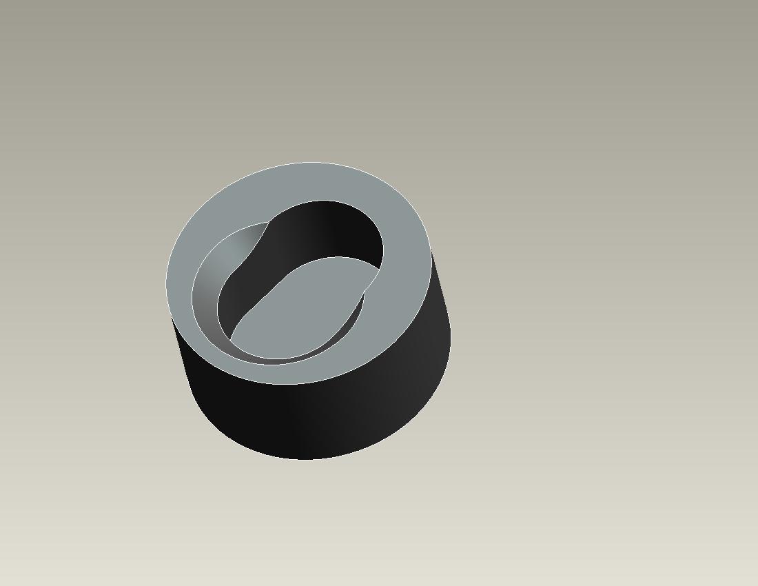
hi,
below i have added two images, if that is what you are looking for then you have to use the swept blend option and two guide curves. the cross section is triangular.

Dec 18, 2012
08:22 AM
- Mark as New
- Bookmark
- Subscribe
- Mute
- Subscribe to RSS Feed
- Permalink
- Notify Moderator
Please log in to access translation
Dec 18, 2012
08:22 AM
Hi All,
Thanks for you help Fixed.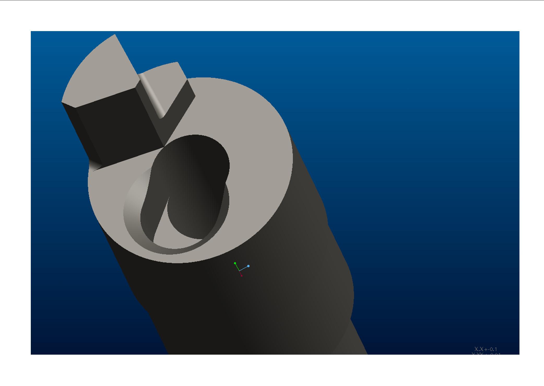
Dec 18, 2012
08:45 AM
- Mark as New
- Bookmark
- Subscribe
- Mute
- Subscribe to RSS Feed
- Permalink
- Notify Moderator
Please log in to access translation
Dec 18, 2012
08:45 AM
Go ahead and mark the answer as correct. Great to hear it!
Dec 19, 2012
06:11 AM
- Mark as New
- Bookmark
- Subscribe
- Mute
- Subscribe to RSS Feed
- Permalink
- Notify Moderator
Please log in to access translation
Dec 19, 2012
06:11 AM
in my last post i had shown two jpegs shwoing the swept blend option to put the cut.
well in pro/engineer also u can use only the chamfer option to get that particular cut. see the image below.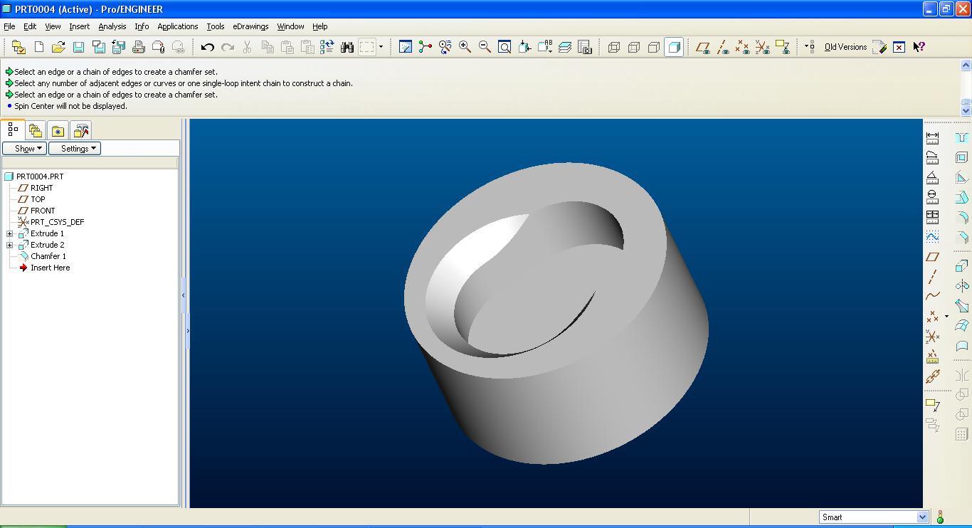
in chamfer select the detail option before selecting the edge and then select only the circular edge..you would get the desired result.
Jan 02, 2013
05:03 PM
- Mark as New
- Bookmark
- Subscribe
- Mute
- Subscribe to RSS Feed
- Permalink
- Notify Moderator
Please log in to access translation
Jan 02, 2013
05:03 PM
Actually, looking at the geometry, and imagining how it would most likely be cut, I'd say a simple revolved cut would be the most accurate and easiest, using the axis of the cylinder on the end there. Most likely (cheapest) the machinest went in there with a simple chamfer tool and plunged to the correct depth, or interpolated a circle. I don't think there's a need for a sweep etc.
Jan 02, 2013
06:16 PM
- Mark as New
- Bookmark
- Subscribe
- Mute
- Subscribe to RSS Feed
- Permalink
- Notify Moderator
Please log in to access translation
Jan 02, 2013
06:16 PM
Looking at the original input (lower right image), there is an obvious elongation of the chamfer path. I think the discussion morphed into a lesser "compromised" solution. As a matter of fact, the chamfer appears to blend tangent to the center "through" hole.
I hate seeing this when the modeling tool is more than adequate to do the job correctly.

Jan 04, 2013
11:26 AM
- Mark as New
- Bookmark
- Subscribe
- Mute
- Subscribe to RSS Feed
- Permalink
- Notify Moderator
Please log in to access translation
Jan 04, 2013
11:26 AM
Well, when I open the attached picture, they look compressed left-to-right. What looks like a circle in the small view gets highly elliptical when you open the pic. You can tell by the fact that even the cylindrical portion in the guy's hands looks elliptical, even the other views look elliptical. Without the part in hand this is one of those things that's hard to pin down. 
Jan 04, 2013
11:37 AM
- Mark as New
- Bookmark
- Subscribe
- Mute
- Subscribe to RSS Feed
- Permalink
- Notify Moderator
Please log in to access translation
Jan 04, 2013
11:37 AM
Hahaha... yep. The forum image processor has a bad habit of compressing images horizontally. Look at the aspect ratio of the post image (lower right image is rectangular) and then enlarge it and the lower right image is square. Another quality software fail