
Turn on suggestions
Auto-suggest helps you quickly narrow down your search results by suggesting possible matches as you type.
Showing results for
Please log in to access translation
Turn on suggestions
Auto-suggest helps you quickly narrow down your search results by suggesting possible matches as you type.
Showing results for
Community Tip - You can Bookmark boards, posts or articles that you'd like to access again easily! X
- Community
- Creo+ and Creo Parametric
- Analysis
- Re: Creating bellows with VSS and trajpar?
Translate the entire conversation x
Please log in to access translation
Options
- Subscribe to RSS Feed
- Mark Topic as New
- Mark Topic as Read
- Float this Topic for Current User
- Bookmark
- Subscribe
- Mute
- Printer Friendly Page
Creating bellows with VSS and trajpar?
Jan 31, 2013
03:12 PM
- Mark as New
- Bookmark
- Subscribe
- Mute
- Subscribe to RSS Feed
- Permalink
- Notify Moderator
Please log in to access translation
Jan 31, 2013
03:12 PM
Creating bellows with VSS and trajpar?
Hey everyone, long time listener first time caller here.
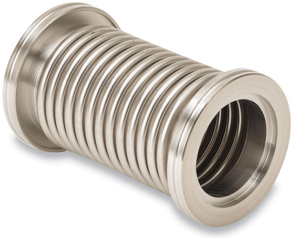
I'm trying to make a model of a hydraulically formed vacuum bellows as shown in the picture below (taken from Kurt Lesker's website).
I can model both flanged ends fine, but I am struggling with the center ruffled section. I could make a revolved section, but that would require sketching out each individual ruffle. I could model a single ruffle and pattern it the necessary number of time to create the part, but what happens if I wanted the part to follow a curve? In short, I'm looking to create the bellows with some elegance, sophistication, and intelligence such that I could potentially make it a flexible part in an assembly or possibly make a family table of bellows (easily). I originally thought a Variable Section Sweep would be the way to go, but I can't get it to work. I will show my current approach below. If someone could tell me why my approach won't work, and give me some advice on how to move forward it would be very much appreciated!
I start with a datum graph of a single rib as shown below (called graph1):
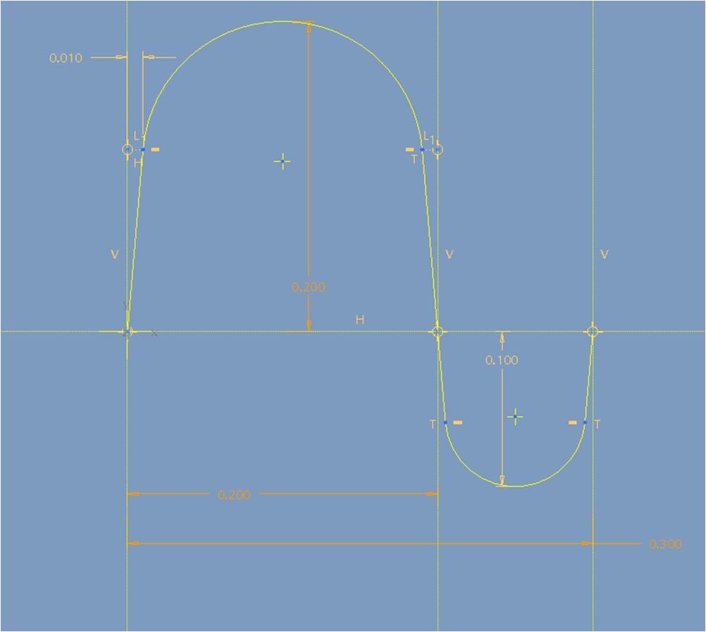
The x-axis represents the nominal diameter of the ruffled section. If I know the x-position of any ruffle section, than I can get the value that I need to add to the nominal diameter from the corresponding y-value on the graph.
To calculate the correct x-value, anywhere on the ruffled section, I use the image below:
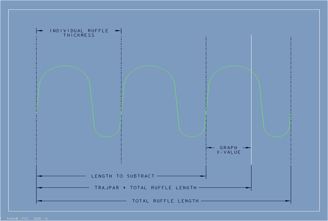
I need the graph x-value. I can get that value by the following formula:
x-value = (trajpar * total_ruffle_length) - length_to_subtract
where:
length_to_subtract = floor( (trajpar*total_ruffle_length) / individual_ruffle_thickness) )
so the general equation (which should work for any number of ruffles and any length of tube) is:
x-value = (trajpar * total_ruffle_length) - floor( (trajpar*total_ruffle_length) / individual_ruffle_thickness)
--
As I write this, my equation is the same thing as using the mod() function:
x-value = mod(trajpar*total_ruffle_length, individual_ruffle_thickness)
--
So I create a Variable Section Sweep with a straight line as the trajectory. I make the section in the sketch as a circle (lets call its diameter sd3). In relations I make the diameter of the circle to be:
sd3 = the_nominal_ruffle_diameter + evalgraph("graph1", x-value)
where the x-value is the value defined above. So the equation should return a y-value of the graph for every trajpar of the line and add it to a nominal diameter. The equation is itself extremely general and is independent of number of ruffles. Logically, this should work (who knows if my logic is in itself logical... but that is a different forum post altogether). Unfortunately... pro/e won't create the sweep. Can anyone help me out as to why? Or how I can create the feature?
Many thanks!
This thread is inactive and closed by the PTC Community Management Team. If you would like to provide a reply and re-open this thread, please notify the moderator and reference the thread. You may also use "Start a topic" button to ask a new question. Please be sure to include what version of the PTC product you are using so another community member knowledgeable about your version may be able to assist.
Labels:
- Labels:
-
General
15 REPLIES 15
Jan 31, 2013
03:47 PM
- Mark as New
- Bookmark
- Subscribe
- Mute
- Subscribe to RSS Feed
- Permalink
- Notify Moderator
Please log in to access translation
Jan 31, 2013
03:47 PM
I only see two problems with your approach... having worked in vacuum products for years. Do not make your next-level assembly models this complex. First of all, you are going to be setting the precedence and second, sustaining a complex piece of geometry will be a headache years down the road. Even though the math is easy on the CPU, the graphics horsepower required will have a negative impact.
Having said that, and if you need a detailed model such as this in only a few specific instances, indeed, make the part as you need for that instance in whatever means that works. I would consider using Warp to quickly form the part to a shape you need on the fly.
In my experience, I would model this as a swept tube (a spline can be straight or curved). You might make the length variable, and you can add instances for various curves. If you really want to maximize utilization, make it a flexible part with the right interfaces to simply fit the tube at the assembly level. ...just not with the convolutions.
If you want it to be representative in the assembly, consider a central tube of the actual material thickness as the minor diameter. On top of this, as a transparent surface or similar thickness solid to represent the OD. Alternatively, put the solid centered in the total thickness and place two transparent surfaces on the ID and OD. You get my drift...
Welcome to the forum!
Jan 31, 2013
06:21 PM
- Mark as New
- Bookmark
- Subscribe
- Mute
- Subscribe to RSS Feed
- Permalink
- Notify Moderator
Please log in to access translation
Jan 31, 2013
06:21 PM
I certainly appreciate everything in your response. To be honest this was more of an experiment to test to see if I could make the bellows with the approach in my original post and if so, to test the stability of such a process (the stability question was quickly answered).
While I will ultimately create the final model using simple tubes to represent the ID and OD of the model as you suggested, modeling the corrugated surface using the Variable Section Sweep has become a bit of a personal battle with Pro/E. I'm not going to roll over that easily, and am willing to commit a bit more of my personal time on this part to try to figure out what is going on. Pride before the fall...
I was able to kind of get my method to work.
The only way I could get the geometry to work was to change the end value on the trajectory to a smaller value as shown (circled in maroon) below:
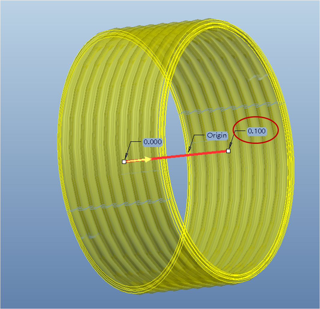
A small range of values work. To be honest I still don't know why this change in values does the trick, or really how those parameters affect the overall model. I will have to do some reading/research on the variable section sweep, but if anyone has a quick explanation it would help put me at ease.
All in all, I think it was a useful introduction into the more powerful features of pro/e (datum graphs, relations, and variable section sweeps), even though the final part may not be useable in any but the most detailed of models.
Jan 31, 2013
07:21 PM
- Mark as New
- Bookmark
- Subscribe
- Mute
- Subscribe to RSS Feed
- Permalink
- Notify Moderator
Please log in to access translation
Jan 31, 2013
07:21 PM
The place I run into most solve issues is in the sketch itself. Even though you can "sneak up" on a particular dimension, you cannot do it in one fail swoop. It is like you sketch some shape and then try to size it. If you change a dim by more that 50%, the sketch either ignores your input or just makes the geometry incompatible. Eventually, you can get the sketch to conform to your will. I suspect the same is happening with your initial sketch in the change. You might be able to make small changes at a time and eventually end up with your end means. For such cases, you must apply limits to your constraining dimensions.
This will be fun to play with. I've done some very powerful things when it comes to bellows using sketches. One thing I always had trouble with was when they go straight (if they are intended to be bent) and when you go past straight (tilt the other way).
Feb 01, 2013
09:48 AM
- Mark as New
- Bookmark
- Subscribe
- Mute
- Subscribe to RSS Feed
- Permalink
- Notify Moderator
Please log in to access translation
Feb 01, 2013
09:48 AM
It's good to see people using advanced features like graphs, especially when linked to a VSS. Bravo Kyle.
While that certainly can be done, I think I'd be more apt, in this case, to simply use a pattern of the bellows and use relations to control things. I'd also make it a family table part, and use a spinal bend to get the curved part after the fact.
Feb 01, 2013
01:55 PM
- Mark as New
- Bookmark
- Subscribe
- Mute
- Subscribe to RSS Feed
- Permalink
- Notify Moderator
Please log in to access translation
Feb 01, 2013
01:55 PM
I forgot about Spinal Bend. That Spinal Bend dialog always gets me.
It certainly is more controllable than Warp but has to be done prior to the fixed/undistorted geometry.
Feb 01, 2013
10:23 AM
- Mark as New
- Bookmark
- Subscribe
- Mute
- Subscribe to RSS Feed
- Permalink
- Notify Moderator
Please log in to access translation
Feb 01, 2013
10:23 AM
Dear Kyle,
Is it not possible with thin revolve feature?
Feb 01, 2013
11:54 AM
- Mark as New
- Bookmark
- Subscribe
- Mute
- Subscribe to RSS Feed
- Permalink
- Notify Moderator
Please log in to access translation
Feb 01, 2013
11:54 AM
A thin revolve feature is definitely possible. When I was first thinking about the different methods available to model the part, I did indeed contemplate using the revolve tool. I decided against it because I thought I could create a more robust, stable, and flexible part by using the Variable Section Sweep tool driven from a graph and relations. Theoretically, my approach should work independently of the number of corrugated ribs, the length of the tube, the diameter of the tube, or the overall shape of the part. The idea was that all you had to do was sketch one rib in a graph, sketch a trajectory, and let pro/e do the rest! While it works great in theory (doesn't everything?), the actual model didn't turn out to be robust, stable, or flexible (bummer).
As it turns out, I think I will go back and try to model the part with a revolve feature, pattern, and spinal bend as suggested by Frank. I've never touched the spinal bend tool, so this will be a good opportunity to try it out.
Feb 01, 2013
02:37 PM
- Mark as New
- Bookmark
- Subscribe
- Mute
- Subscribe to RSS Feed
- Permalink
- Notify Moderator
Please log in to access translation
Feb 01, 2013
02:37 PM
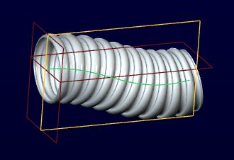
Let's see what you guys think of the attached.
The Spinal Bend trajectory is a spline with 3 controlling values. The convolution is drag-able with the handle between the two arcs. Convolution section is a bit, well... convoluted and can be simplified but the Spinal Bend is particular about the starting location. In general, the overall scheme would be a bit more controlled, defined and refined.
If the spine sketch could be made "flexible" for the next level assembly, you would have a good flexible connector. I'd be interested in how this can be accomplished down to a tutorial level. I have no clue as to how flexible parts are managed in real life. I've seen the spring examples.

Feb 01, 2013
03:32 PM
- Mark as New
- Bookmark
- Subscribe
- Mute
- Subscribe to RSS Feed
- Permalink
- Notify Moderator
Please log in to access translation
Feb 01, 2013
03:32 PM
Thanks for the update! Your model looks pretty impressive from the images that you attached. Unfortunately, I was unable to open the part file because there is some incompatibility with your file and my version of pro/e (I get a bang saying that you made the model with a newer version of pro/e than I have running).
From the images alone, I think you left enough bread crumbs for me to follow your steps. I will try to replicate what you have; that is if I can figure out this spinal bend prompt! I started using pro/e after PTC started hiding the menu manager, and as such I really don't have much experience working with it. I'll let you know if I come up with anything to contribute to the approach that you used.
Feb 01, 2013
07:32 PM
- Mark as New
- Bookmark
- Subscribe
- Mute
- Subscribe to RSS Feed
- Permalink
- Notify Moderator
Please log in to access translation
Feb 01, 2013
07:32 PM
The only thing not shown is the pattern (10x) which is driven from a sketch reference dimension that is applied to the pattern offset. This is how the initial shape can be stretched and compressed by manipulating the convolution sketch without the pattern failing.
I really should load WF4 so I can make compatible samples 
Feb 04, 2013
11:02 AM
- Mark as New
- Bookmark
- Subscribe
- Mute
- Subscribe to RSS Feed
- Permalink
- Notify Moderator
Please log in to access translation
Feb 04, 2013
11:02 AM
Nice job Antonius, exactly what I was thinking. The part could be made flexible, with the angle and location of one end being variable as needed.
I've found Warp to be almost useless, as you cannot manipulate the geometry with hard numbers, like you can with a spinal bend. I've been able to do some really cool stuff with spinal bends (I added another pic to my abum of a flex circuit), though I think a SIGNIFICANT enhancement (are you listening PTC?) would be to be able to bend a part or especially an assembly at an upper assembly level. I had to go through all kinds of monkey business to get what I needed (part family tables and assembly family tables). I think warp is best used for creating models for later use in animation software. Although why not just manipulate it there? But I digress. But, recently, I DID find a use for a Warp feature, and put it in my photo album as the last pic. Yes, I couldn't Warp it to a value, but in this case I didn't need to, I just did it for show, eyeballing it to get what I wanted. and in that case it was easy and worked very well.
Feb 04, 2013
11:39 AM
- Mark as New
- Bookmark
- Subscribe
- Mute
- Subscribe to RSS Feed
- Permalink
- Notify Moderator
Please log in to access translation
Feb 04, 2013
11:39 AM
I looked up Tweak Features in the help files. I never even knew they existed. I suspect the Warp feature replaced several of these since you have to specifically turn a handful of them on. These too have a very cryptic interface.
Feb 04, 2013
12:10 PM
- Mark as New
- Bookmark
- Subscribe
- Mute
- Subscribe to RSS Feed
- Permalink
- Notify Moderator
Please log in to access translation
Feb 04, 2013
12:10 PM
Antonius, I was able to recreate your version of the model. Thanks for all of the help, I can now sleep at night knowing that it is possible to create an accurate bellows. Per your original post I agree that a simplified part should probably be used when possible, and only use the detailed version when absolutely necessary.
It would be kind of nice if Simplified Reps at the part level was a little bit more versatile (unless I am missing something. At the part level, I can never get simplified reps to do exactly what I want). One could model both the non-detailed and detailed version in one part. The default rep could be the non-detailed version, and the user could turn on the detailed version quickly and easily through changing the rep of the part if needed. If a part was carefully modeled (by adding in some intelligent relations), you could make a specific sized bellows, check it into a library, and use it in many different assemblies without having to make any changes to the model. This would keep the number of instances of a specific bellows part down to a minimum (ideally one).
I know what you're going to say... Managing that part down the road will turn out to be a major headache at best. I don't disagree, but I just had to spend some time in the "ideal CAD world" for a few minutes. Thanks again to both you and Frank, I learned quite a bit in the process of making this model.
Feb 04, 2013
12:28 PM
- Mark as New
- Bookmark
- Subscribe
- Mute
- Subscribe to RSS Feed
- Permalink
- Notify Moderator
Please log in to access translation
Feb 04, 2013
12:28 PM
Glad it worked out, Kyle.
FWIW... PTC did come up with "shrink wrap". It is suppose to do part of what you are asking for. Flexible parts are suppose to deal with minimizing the configurable options of a specific part. This is the way the spring works today as an example. Add the two together and you might just get your perfect system. I don't know if it can be done today, or if anyone is actually doing it. And then you have the family table to make use of either the corrugations or the tube. I think they are pretty close already. The only remaining question is, are you disciplined enough to make this wart work for you at every level.
Feb 04, 2013
11:05 AM
- Mark as New
- Bookmark
- Subscribe
- Mute
- Subscribe to RSS Feed
- Permalink
- Notify Moderator
Please log in to access translation
Feb 04, 2013
11:05 AM
Spinal Bend is a very powerful, very old feature. It's kind of difficult to understand at first, especially with the "volume to bend" prompt. I posted up on it earlier with a part I did, I'll try and find the link later. antonius has a good example of what I was thinking of for you.
Announcements


Top Tags
