
Turn on suggestions
Auto-suggest helps you quickly narrow down your search results by suggesting possible matches as you type.
Showing results for
Please log in to access translation
Turn on suggestions
Auto-suggest helps you quickly narrow down your search results by suggesting possible matches as you type.
Showing results for
Community Tip - Did you get an answer that solved your problem? Please mark it as an Accepted Solution so others with the same problem can find the answer easily. X
- Community
- Creo+ and Creo Parametric
- Analysis
- Re: Force to close a
Translate the entire conversation x
Please log in to access translation
Options
- Subscribe to RSS Feed
- Mark Topic as New
- Mark Topic as Read
- Float this Topic for Current User
- Bookmark
- Subscribe
- Mute
- Printer Friendly Page
Force to close a
Apr 10, 2018
03:45 AM
- Mark as New
- Bookmark
- Subscribe
- Mute
- Subscribe to RSS Feed
- Permalink
- Notify Moderator
Please log in to access translation
Apr 10, 2018
03:45 AM
Force to close a
Goodmorning,
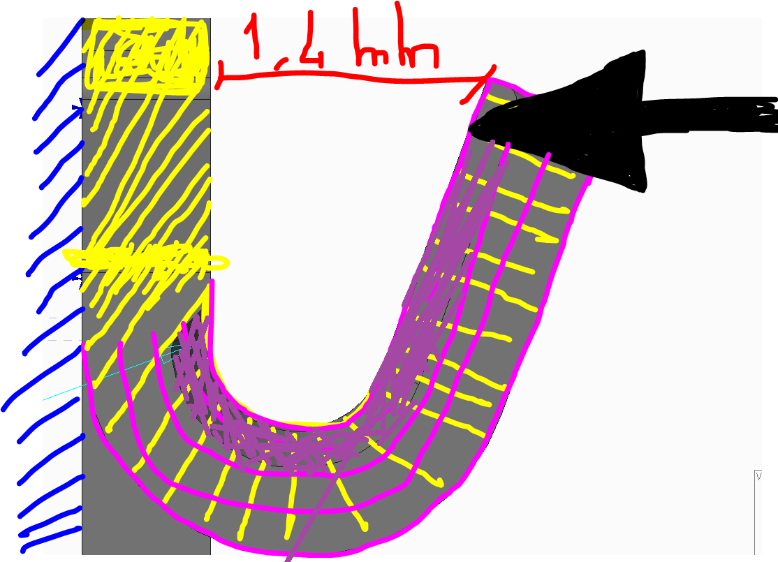
I have a following question: Is it possibile investigate with Creo Simulate the value of the force in order to "close"
the purple solid against the Yellow solid.I need a non-linear analisys, right?
Thank you for your help
20 REPLIES 20
Apr 10, 2018
09:34 AM
- Mark as New
- Bookmark
- Subscribe
- Mute
- Subscribe to RSS Feed
- Permalink
- Notify Moderator
Please log in to access translation
Apr 10, 2018
09:34 AM
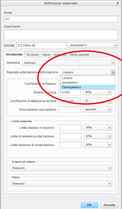
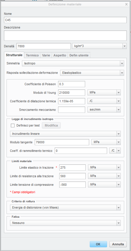
Yes you want non-linear. Large Deformation and possibly Elasto-plastic material
Here is the difference in small displacement and Large displacement (small on left)

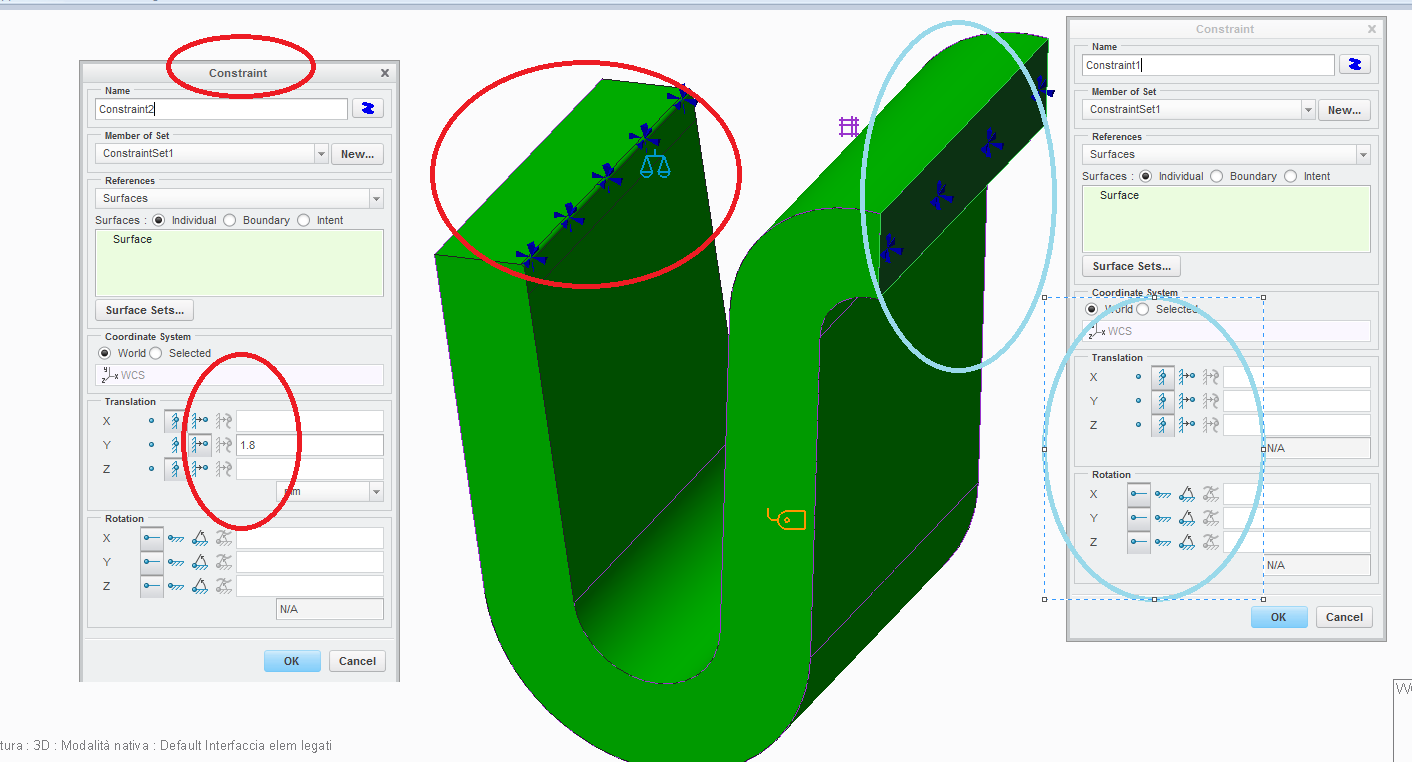
Here is how you do the 1.4mm deflection

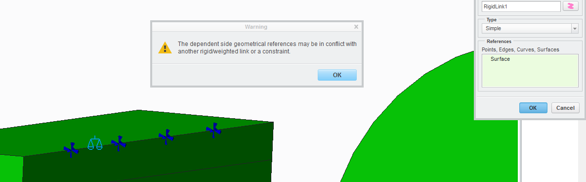
Here is how you prevent infinite stress at the edge constraint... with a small region made rigid.

Here is the measure used to obtain the force.

Here are the Analysis definitions. If using elasto-plastic material then Plasticity will have a check mark.


Plotting the measure vs. time

Final results. If stress is above yield then you should use ELASTO-PLASTIC material. Nonlinear material + non-linear geometry. Otherwise force is generally predicted too high.

Confirmation? Run this model with found force (48N in this case) in X direction as a load in place of the enforced displacement. Confirm max displacement about 1.4mm in X direction.
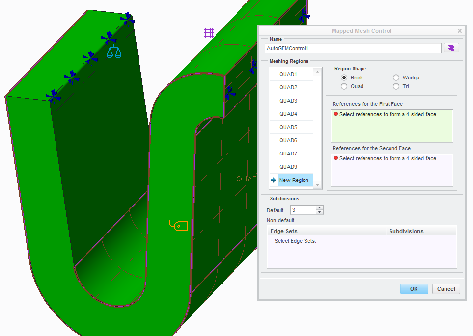
BONUS - I used a Mapped Mesh (not totally necessary but results are so smooooth!)


Apr 10, 2018
12:26 PM
- Mark as New
- Bookmark
- Subscribe
- Mute
- Subscribe to RSS Feed
- Permalink
- Notify Moderator
Please log in to access translation
Apr 10, 2018
12:26 PM
Thank you for a good response
but I'm not able to open the file.....
Apr 10, 2018
01:09 PM
- Mark as New
- Bookmark
- Subscribe
- Mute
- Subscribe to RSS Feed
- Permalink
- Notify Moderator
Please log in to access translation
Apr 10, 2018
01:09 PM
That is why I had all the details... because not everyone is using the same version.
Feb 13, 2019
08:47 AM
- Mark as New
- Bookmark
- Subscribe
- Mute
- Subscribe to RSS Feed
- Permalink
- Notify Moderator
Please log in to access translation
Feb 13, 2019
09:04 AM
- Mark as New
- Bookmark
- Subscribe
- Mute
- Subscribe to RSS Feed
- Permalink
- Notify Moderator
Please log in to access translation
Feb 13, 2019
10:05 AM
- Mark as New
- Bookmark
- Subscribe
- Mute
- Subscribe to RSS Feed
- Permalink
- Notify Moderator
Please log in to access translation
Feb 13, 2019
10:05 AM
Simulate said me that costraint and rigid link on surface region to prevent infinity stress is incompatible...
Feb 13, 2019
10:52 AM
- Mark as New
- Bookmark
- Subscribe
- Mute
- Subscribe to RSS Feed
- Permalink
- Notify Moderator
Please log in to access translation
Feb 13, 2019
10:52 AM
This is OK. It is a warning, not an error. Only use caution when this message appears because you may be asking the model to do two different things at same time.
Feb 13, 2019
10:57 AM
- Mark as New
- Bookmark
- Subscribe
- Mute
- Subscribe to RSS Feed
- Permalink
- Notify Moderator
Please log in to access translation
Feb 13, 2019
10:57 AM
What You do in your model? You used the same way or an other?
Feb 13, 2019
11:24 AM
- Mark as New
- Bookmark
- Subscribe
- Mute
- Subscribe to RSS Feed
- Permalink
- Notify Moderator
Please log in to access translation
Feb 13, 2019
11:24 AM
Same way.
Feb 14, 2019
06:03 AM
- Mark as New
- Bookmark
- Subscribe
- Mute
- Subscribe to RSS Feed
- Permalink
- Notify Moderator
Please log in to access translation
Feb 14, 2019
06:03 AM
Hi!
I used an elastoplastic material, but obtain this warning message with high stress
Feb 14, 2019
08:19 AM
- Mark as New
- Bookmark
- Subscribe
- Mute
- Subscribe to RSS Feed
- Permalink
- Notify Moderator
Please log in to access translation
Feb 14, 2019
08:19 AM
Please show more views of your model. Is there a location with a sharp inside corner like this?
All inside corners near areas of interest should have at least a small radius. For the plastic parts I work with 0.15mm radius is used. Compared to H-elements, P-elements are less forgiving. In H-elements the stress is averaged over the element size which hides the singularity until using smaller and smaller elements. For P-elements the order of the element captures the high stress with larger elements. You can artificially limit the order of the elements near singularities but I prefer a tiny, but realistic radius.
What strain is it reporting vs. what you expect? Are you using a force or an enforced displacement. With a force this same message often comes when the design cannot reach the load applied, sometimes even failing to finish the loadsteps. I also suggest to plot a measure of plastic strain or stress vs loadstep. You can stop the analysis and view intermediate results at each loadstep.
Finally element quality/number will affect the ability to model large strains. A mapped mesh with quads and more layers through the thickness will help capture larger strains without too much element distortion. A tetra mesh with large elements could contribute to the issue.

Feb 18, 2019
04:01 AM
- Mark as New
- Bookmark
- Subscribe
- Mute
- Subscribe to RSS Feed
- Permalink
- Notify Moderator
Please log in to access translation
Feb 18, 2019
04:01 AM
Hi,
I try to improve my model, but I obtain again high stresses;
I added a small radius where the displacement occurs and mapped mesh
Feb 18, 2019
04:34 AM
- Mark as New
- Bookmark
- Subscribe
- Mute
- Subscribe to RSS Feed
- Permalink
- Notify Moderator
Please log in to access translation
Feb 18, 2019
04:34 AM

Feb 18, 2019
04:54 AM
- Mark as New
- Bookmark
- Subscribe
- Mute
- Subscribe to RSS Feed
- Permalink
- Notify Moderator
Please log in to access translation
Feb 18, 2019
04:54 AM

In solid mechanics, the shear modulus or modulus of rigidity, denoted by G, or sometimes S or μ, is a measure of the elastic shear stiffness of a material and is defined as the ratio of shear stress to shear strain:[1] The derived SI unit of shear modulus is the pascal (Pa), although it is usually
Feb 18, 2019
05:20 AM
- Mark as New
- Bookmark
- Subscribe
- Mute
- Subscribe to RSS Feed
- Permalink
- Notify Moderator
Please log in to access translation
Feb 18, 2019
05:20 AM
no

Feb 18, 2019
06:09 AM
- Mark as New
- Bookmark
- Subscribe
- Mute
- Subscribe to RSS Feed
- Permalink
- Notify Moderator
Please log in to access translation
Feb 18, 2019
06:09 AM
In this way the values of stress down, but there is again the warning
"** Warning:
The stress is much higher than the yield strength of one of the
elasto-plastic materials in your analysis. Please review
your material properties and/or units."
Feb 18, 2019
08:27 AM
- Mark as New
- Bookmark
- Subscribe
- Mute
- Subscribe to RSS Feed
- Permalink
- Notify Moderator
Please log in to access translation
Feb 18, 2019
08:27 AM

Feb 20, 2019
04:21 AM
- Mark as New
- Bookmark
- Subscribe
- Mute
- Subscribe to RSS Feed
- Permalink
- Notify Moderator
Please log in to access translation
Feb 20, 2019
04:21 AM
Where did you find this value (1000)?
The data sheet I mean.
Thanks
Feb 20, 2019
07:06 AM
- Mark as New
- Bookmark
- Subscribe
- Mute
- Subscribe to RSS Feed
- Permalink
- Notify Moderator
Please log in to access translation
Feb 20, 2019
07:06 AM
it's approximately, circa

Apr 26, 2018
08:56 AM
- Mark as New
- Bookmark
- Subscribe
- Mute
- Subscribe to RSS Feed
- Permalink
- Notify Moderator
Please log in to access translation

Announcements


Top Tags
