
Turn on suggestions
Auto-suggest helps you quickly narrow down your search results by suggesting possible matches as you type.
Showing results for
Please log in to access translation
Turn on suggestions
Auto-suggest helps you quickly narrow down your search results by suggesting possible matches as you type.
Showing results for
Community Tip - Did you get an answer that solved your problem? Please mark it as an Accepted Solution so others with the same problem can find the answer easily. X
- Community
- Creo+ and Creo Parametric
- Analysis
- Re: Getting fasteners to work
Translate the entire conversation x
Please log in to access translation
Options
- Subscribe to RSS Feed
- Mark Topic as New
- Mark Topic as Read
- Float this Topic for Current User
- Bookmark
- Subscribe
- Mute
- Printer Friendly Page
Getting fasteners to work
Apr 04, 2016
09:23 AM
- Mark as New
- Bookmark
- Subscribe
- Mute
- Subscribe to RSS Feed
- Permalink
- Notify Moderator
Please log in to access translation
Apr 04, 2016
09:23 AM
Getting fasteners to work
So, inspired by Roland Jakel's presentation, I thought I'd revisit an old analysis and try to re-run it using the fastener functionality.
Unfortunately, the analysis ran with "The fastener is invalid" warnings, and resulted in no loads (despite specifying preload).
The model is slightly unusual in that there is a deliberate gap which the bolts should pull down once tightened, so I closed the gap to make the surfaces coincident, but this made no difference.
The clearance holes are chamfered on both sides, so I suppressed these chamfers (and reinstated the gap) then redefined the fastener references, only to be told that "The fastener references cannot lie on the contacting surfaces." Well, a) there's a gap so technically the surfaces aren't contacting, and b) how else am I supposed to select the references, if I can't select the open edge of the tapped hole?
On a related note, it tells me that I can't put a 6 mm fastener into my M6 tapped (Ø5) hole - should I be modelling my tapped holes at the major diameter, or is the root diameter of the screw thread appropriate?
Solved! Go to Solution.
ACCEPTED SOLUTION
Accepted Solutions
Apr 04, 2016
04:07 PM
- Mark as New
- Bookmark
- Subscribe
- Mute
- Subscribe to RSS Feed
- Permalink
- Notify Moderator
Please log in to access translation
Apr 04, 2016
04:07 PM
Hi Jonathan,
could you provide an image of your assembly or the model itself? There may be several reasons why you obtain various errors when using the Simulate fastener feature, so I can just speculate. First of all some remarks:
- You must bolt exactly two different parts together – three or more (e.g. two flanges and additional washer(s)) don’t work, neither does 1 single part bolted with itself, like a clamp
- If there is a gap between the flanges in contact (what you state), the algorithm that detects the contacting surfaces cannot find the flange interstice, and a warning should be issued
- Unusual part geometry may also prevent the algorithm from detecting contacting surfaces at the flange interstice correctly. Also, a volume region applied there may be responsible for that. You should obtain a GUI message what’s up.
- Yes, fastener (threaded) holes must have at least the nominal fastener diameter, you have to change the Pro/E-model accordingly.
- You may have used wrong references or wrongly applied “bolt” or “screw” type fasteners. E.g., you cannot use the cosmetic surface used as thread representation as reference
I guess a volume bolt and the preload element would be a better choice to solve your problem, but I have to see the model to judge.
According to my experience, the fastener feature in Creo 2 works relatively robust now. I filed some cases leading to SPRs approx. two years ago, but those should be fixed in the meantime. I remember there was (and may be still is, I don’t remember exactly) a problem if you mix fasteners with linear and contact interfaces in one model, but this should not be responsible for the trouble you are facing.
From Altran side, we offer a special 3-day workshop how to do fastener analysis with Creo Simulate: This consists of a 1-day workshop in nonlinear contact analysis and a 2-day-workshop in fastener theory and application. This may be helpful for users that want to become familiar with this topic. Analyzing fasteners with a FEM code correctly is more difficult as many users believe.
Best regards,
Roland
9 REPLIES 9
Apr 04, 2016
04:07 PM
- Mark as New
- Bookmark
- Subscribe
- Mute
- Subscribe to RSS Feed
- Permalink
- Notify Moderator
Please log in to access translation
Apr 04, 2016
04:07 PM
Hi Jonathan,
could you provide an image of your assembly or the model itself? There may be several reasons why you obtain various errors when using the Simulate fastener feature, so I can just speculate. First of all some remarks:
- You must bolt exactly two different parts together – three or more (e.g. two flanges and additional washer(s)) don’t work, neither does 1 single part bolted with itself, like a clamp
- If there is a gap between the flanges in contact (what you state), the algorithm that detects the contacting surfaces cannot find the flange interstice, and a warning should be issued
- Unusual part geometry may also prevent the algorithm from detecting contacting surfaces at the flange interstice correctly. Also, a volume region applied there may be responsible for that. You should obtain a GUI message what’s up.
- Yes, fastener (threaded) holes must have at least the nominal fastener diameter, you have to change the Pro/E-model accordingly.
- You may have used wrong references or wrongly applied “bolt” or “screw” type fasteners. E.g., you cannot use the cosmetic surface used as thread representation as reference
I guess a volume bolt and the preload element would be a better choice to solve your problem, but I have to see the model to judge.
According to my experience, the fastener feature in Creo 2 works relatively robust now. I filed some cases leading to SPRs approx. two years ago, but those should be fixed in the meantime. I remember there was (and may be still is, I don’t remember exactly) a problem if you mix fasteners with linear and contact interfaces in one model, but this should not be responsible for the trouble you are facing.
From Altran side, we offer a special 3-day workshop how to do fastener analysis with Creo Simulate: This consists of a 1-day workshop in nonlinear contact analysis and a 2-day-workshop in fastener theory and application. This may be helpful for users that want to become familiar with this topic. Analyzing fasteners with a FEM code correctly is more difficult as many users believe.
Best regards,
Roland
Apr 05, 2016
03:53 AM
- Mark as New
- Bookmark
- Subscribe
- Mute
- Subscribe to RSS Feed
- Permalink
- Notify Moderator
Please log in to access translation
Apr 05, 2016
03:53 AM
Hi Roland,
Thank you for taking the time to reply.
I think my problem is the "exactly two parts" requirement - I have three, and although they're not in series like a bolt and a washer, I suspect this is the root cause of my problem. It looks like this is not an appropriate model to experiment with fasteners!
I'll go and try out the preload element, though, as that could be useful to understand.
Thanks again,
Jonathan
Jun 14, 2017
12:25 PM
- Mark as New
- Bookmark
- Subscribe
- Mute
- Subscribe to RSS Feed
- Permalink
- Notify Moderator
Please log in to access translation
Jun 14, 2017
12:25 PM
Jonathan,
That is something being preloaded. We so that all the time, usually bearings.
Roland,
I 'bolt' lots of bits together and it behaves well (don't know about Creo 4 yet). We just need springs to stop parts from being squeezed out like a bar of soap.
Just thoughts ...
Jun 01, 2017
06:50 AM
- Mark as New
- Bookmark
- Subscribe
- Mute
- Subscribe to RSS Feed
- Permalink
- Notify Moderator
Please log in to access translation
Jun 01, 2017
06:50 AM
Hello Roland
The topic is now more than a year old but to complement the problem that Jonathan got I may have another example of "The fastener is invalid. Please redefine the fastener." in Creo 2.0 M180.
I had a situation that mix contact interface and screw with preload in a flange. And I was having problems to run it.
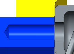
So I created a simple CAD file to test (picture below).
If a groove is present you may get the "invalid fastener message" and the simulation will ignore any bolt/screw. Thus you may take a lot of time to figure out why because when introducing the screws during FEM setup everything goes well and without any warning.
I´m not sure if this is a particular geometry/situation that confuses the software (bug?) or it is a known limitation. I have not tested but this issue may cause problem if you want to test flanges with an o-ring groove for example. So far the above geometry should be a valid one for bolted interfaces.
Also I´m using your 2013 bolted connections presentation to learn and to avoid at maximum any pitfalls. Indeed to correctly interpret fasteners results in FEM is not something trivial.
However I was surprised to read only here that until now I was using the wrong screw diameter. Creo represents automatically a metric screw hole with the drill diameter. I was considering it roughly as an approximation of the screw´s minor diameter - a conservative approach.
For example an M6 hole has actually a D:5mm hole and thus Creo creates a screw with D:5mm - but I read here that the correct iss to simulate for example a metric screw is to create a nominal hole and set the screw to the same diameter (major diameter).
Another small detail in your presentation is that you cannot check "include preload" and still put it "0". The software does not accept this (value must be > 0).
If you have a lot of screws in assembly the best is to define preload as a parameter - since in Creo 2 it is necessary to run an extra loop to determine the effective preload due to connection stiffness and after apply the necessary correction in the preload value - a lot of work if you need to update the value manually.
Here I miss also a way to pattern bolts/screws in FEM.
Best regards
R. Rabe
Jun 14, 2017
10:14 AM
- Mark as New
- Bookmark
- Subscribe
- Mute
- Subscribe to RSS Feed
- Permalink
- Notify Moderator
Please log in to access translation
Jun 14, 2017
11:11 AM
- Mark as New
- Bookmark
- Subscribe
- Mute
- Subscribe to RSS Feed
- Permalink
- Notify Moderator
Please log in to access translation
Jun 14, 2017
11:11 AM
I´m not sure what do you mean with your example - but I was surprised to see that the simulation works.
My Interpretation is that it is an assembly that should be invalid for fastener analysis (based on Creo help file pictured below) - but actually Creo 2.0 runs it without any warning about invalid fasteners or contacts - and provides you all the result considering screws and contact surfaces! So actually I´m not sure anymore what is a "valid" fastener assembly because Creo example was clear enough.
So, what is going on? Is this a valid or invalid simulation?

Taking the chance, complementing my original message, I figure out that a simply cut in the contact surface is enough to Creo complete the simulation without the “The fastener is invalid. Please redefine the fastener” message. I already sent this example to PTC support and I´m waiting for a feedback.

Best regards
R. Rabe
Jun 16, 2017
03:07 AM
- Mark as New
- Bookmark
- Subscribe
- Mute
- Subscribe to RSS Feed
- Permalink
- Notify Moderator
Please log in to access translation
Jun 16, 2017
03:07 AM
Hello,
- creo help is not up to date (obsolete).
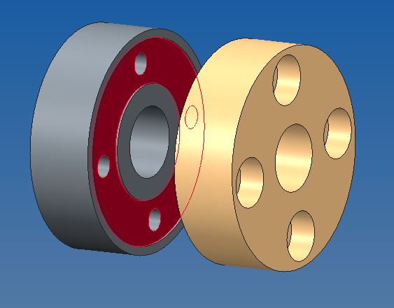
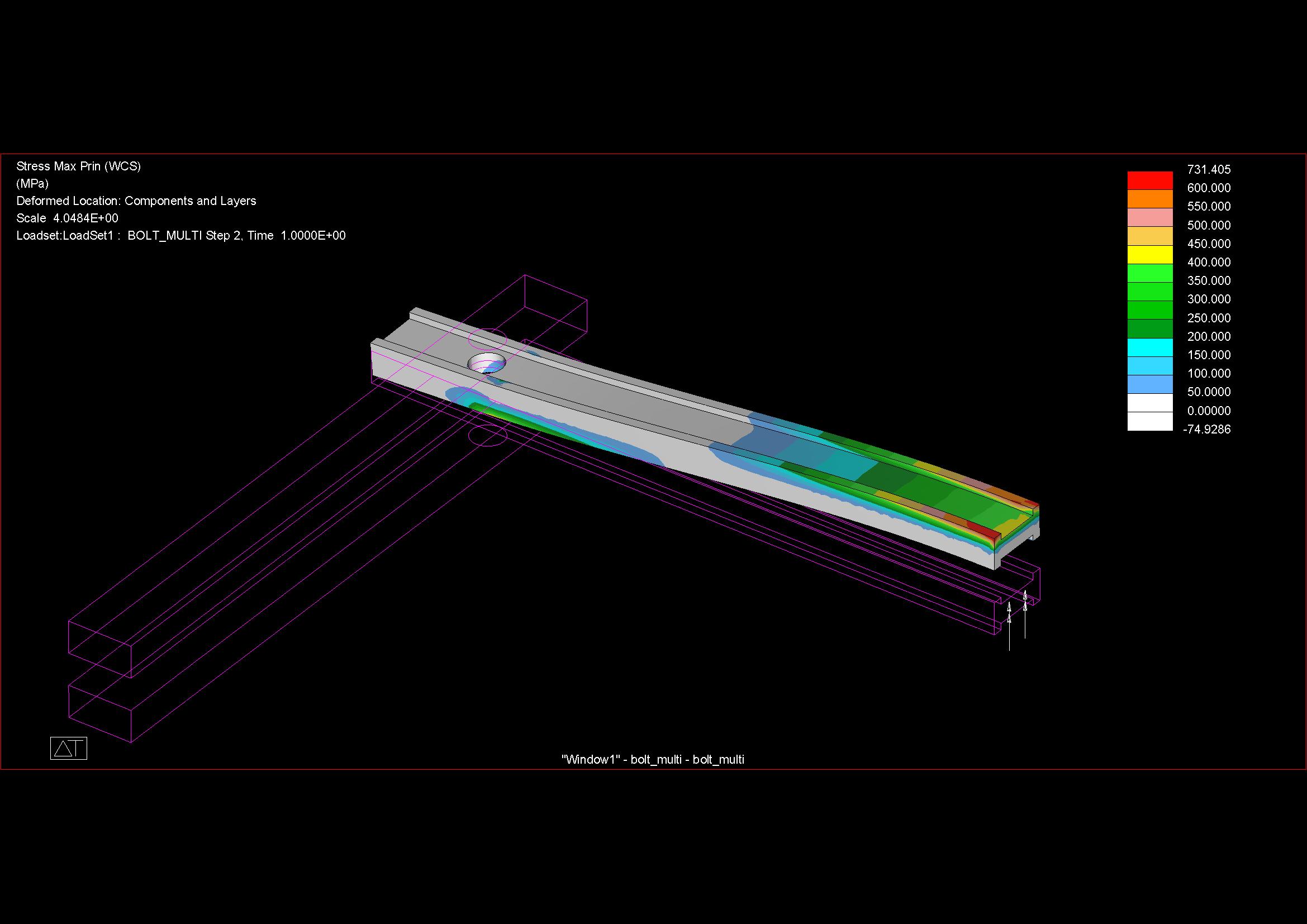
- a example for a clamp with more parts is attached.
workarounds: CTRL+C, then CTRL+V etc.; user defined parameter, for example:
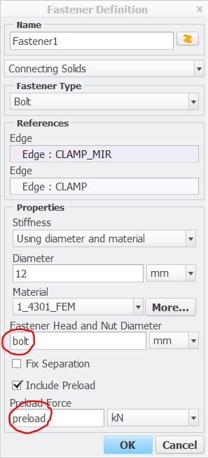
regards
paul
Jun 14, 2017
12:18 PM
- Mark as New
- Bookmark
- Subscribe
- Mute
- Subscribe to RSS Feed
- Permalink
- Notify Moderator
Please log in to access translation
Jun 14, 2017
12:18 PM
Hi,
fastener diameter is automatically the same as the hole diameter
The head diameter is automatically 1.7 x fastener (hole)
The separation test diameter is automatically 2 x fastener (hole)
Separation test diameter becomes irrelevant if contact is used
All diameters may be adjusted manually after references are selected
Fastener diameter is best manually adjusted to stress diameter after selection of hole references and for an M5 this is about 4.25mm, where the hole would be somewhere between 5.3 and 5.8mm depending on design.
If you are not using contact then the automatic separation test diameter could be too big and run off the edge of the part or meet another feature.
Likewise, the automatic head diameter may be bigger than your counterbore.
Both of these may cause failure.
Of course, your problem could be something else ...
Can you upload the model for us to play with?
Additionally, there is no patterning for fasteners. Frustrating but true. Use map keys to minimise effort; it's a reasonable compromise
Additionally, there is always an 'extra loop' to determine preloads, it doesn't matter what software you use. The question is whether you ask for the software to do this adjustment for you 'account for stiffness' (such that it quietly does it in the background taking twice as long and leaving you with no idea about what the preload needs to be changed to in order to avoid the additional time)* OR you perform an explicit separate analysis to determine the preloads required to account for structural stiffness such that any subsequent studies are truly single analyses.
Comment. Parameters are fine but consider what happens if someone else reviews your model. It may be generally better if the fastener information is up front and centre. The 'fancier' the model the more trouble it can be.
*Surely there must be a way of finding out what the internal values for preload are set to?? It is really useful information. I wanted Creo to reset the fastener preload values for me after accounting for stiffness but I continue to cut and paste from a spreadsheet. Account for stiffness is cheaper if one intends only one calculation. It's a guarantee that you will do many calculations.
atb
Jun 16, 2017
03:37 AM
- Mark as New
- Bookmark
- Subscribe
- Mute
- Subscribe to RSS Feed
- Permalink
- Notify Moderator
Please log in to access translation
Jun 16, 2017
03:37 AM
Charles,
a workaround (sometimes) for a pattern of fastener:
regards
paul
Announcements


Top Tags
