Community Tip - Did you know you can set a signature that will be added to all your posts? Set it here! X
- Community
- Creo+ and Creo Parametric
- Analysis
- Re: Problems with Mechanism Connections
- Subscribe to RSS Feed
- Mark Topic as New
- Mark Topic as Read
- Float this Topic for Current User
- Bookmark
- Subscribe
- Mute
- Printer Friendly Page
Problems with Mechanism Connections
- Mark as New
- Bookmark
- Subscribe
- Mute
- Subscribe to RSS Feed
- Permalink
- Notify Moderator
Problems with Mechanism Connections
All,
I'm having some trouble with Mechanism functioning properly and I'm hoping you can help solve my problems. Refer to the images below.
I have a subassembly (called top_cover_2.asm) which includes the following items...plate, bearing assembly, and motor assembly (which has 2 adaptors and a servo motor assembly). The bearing assembly and the servo motor assembly have been defined as pin joints to allow rotational motion. The top_cover_2 assembly gets attached to a frame part (3245298-002.prt). Once attached, I need to attach a clevis bracket which completes the connection from the bottom half of the motor back to the frame.
The problem originates when I try to attach this clevis bracket, it locks all rotational motion even though the top half of the servo motor should be able to rotate with the upper coupler, turntable, and outer bearing race. If I don't attach the clevis bracket, I can rotate the outer bearing race but the entire motor (top and bottom half) will rotate also, which is not how the system should function.
Could somebody take a look at my files and see if you can fix the problem? I have had no success yet after trying a bunch of different things. I'm running Creo 2 M150.
I attached 2 pictures...it wouldn't let me imbed them.
The top level assembly is called TROUBLESHOOT_ASM.asm
This thread is inactive and closed by the PTC Community Management Team. If you would like to provide a reply and re-open this thread, please notify the moderator and reference the thread. You may also use "Start a topic" button to ask a new question. Please be sure to include what version of the PTC product you are using so another community member knowledgeable about your version may be able to assist.
Solved! Go to Solution.
Accepted Solutions
- Mark as New
- Bookmark
- Subscribe
- Mute
- Subscribe to RSS Feed
- Permalink
- Notify Moderator
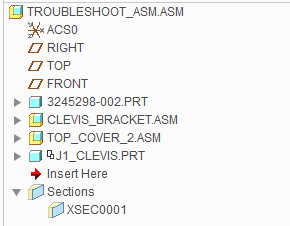
I got the problem solved. I finally heard back from a PTC engineer and he was able to redefine the connection of the motor assembly (8179-2.asm) to the turntable (T7_TURNTABLE.prt) inside TOP_COVER_2.ASM using a total of 3 general style mechanism constraints. The first 2 general constraints (in constraint set #1) were an insert and a mate (to set the depth of the motor assembly with respect to the turntable). The second constraint set was a general constraint to set the clocking of the motor assembly at the keyway surfaces.
The clevis rod (J1_CLEVIS.PRT) was then modified to have 2 constraints. Basically they were insert connections between the rod ends and the spherical bushings.
New model tree should look as follows...

Thanks anyways for the help Tom.
- Mark as New
- Bookmark
- Subscribe
- Mute
- Subscribe to RSS Feed
- Permalink
- Notify Moderator
Something is going on with the motor's internal connection. When assembled into the top cover assembly it loses it ability to rotate. Trying to figure out why...
- Mark as New
- Bookmark
- Subscribe
- Mute
- Subscribe to RSS Feed
- Permalink
- Notify Moderator
I got the problem solved. I finally heard back from a PTC engineer and he was able to redefine the connection of the motor assembly (8179-2.asm) to the turntable (T7_TURNTABLE.prt) inside TOP_COVER_2.ASM using a total of 3 general style mechanism constraints. The first 2 general constraints (in constraint set #1) were an insert and a mate (to set the depth of the motor assembly with respect to the turntable). The second constraint set was a general constraint to set the clocking of the motor assembly at the keyway surfaces.
The clevis rod (J1_CLEVIS.PRT) was then modified to have 2 constraints. Basically they were insert connections between the rod ends and the spherical bushings.
New model tree should look as follows...

Thanks anyways for the help Tom.
- Mark as New
- Bookmark
- Subscribe
- Mute
- Subscribe to RSS Feed
- Permalink
- Notify Moderator
Interesting. I have seen issues in the past with insert connections causing issues. The "allow assumptions" seems to create a hidden constraint back to the global coordinate system that can lock things up.
I've actually whittled this down to just the motor halves and the bearing (using only planar constraints) and I'm still getting the error. It's really bugging me now, so maybe I'll open my own case with tech support. (If you can tell me your case number or tech's name, I will try to reference that.)
- Mark as New
- Bookmark
- Subscribe
- Mute
- Subscribe to RSS Feed
- Permalink
- Notify Moderator
PTC Case C12653679
Mark Fahlbeck was my engineer.
- Mark as New
- Bookmark
- Subscribe
- Mute
- Subscribe to RSS Feed
- Permalink
- Notify Moderator
Thanks. Turned out to be the same issue. Connecting the one assembly to the other required the use of mechanism connections, not placement constraints, even though the assembly was not moving relative to the assembly it was being placed into.


