Community Tip - Visit the PTCooler (the community lounge) to get to know your fellow community members and check out some of Dale's Friday Humor posts! X
- Community
- Creo+ and Creo Parametric
- Analysis
- Re: Simulation of a beam on two simple supports
- Subscribe to RSS Feed
- Mark Topic as New
- Mark Topic as Read
- Float this Topic for Current User
- Bookmark
- Subscribe
- Mute
- Printer Friendly Page
Simulation of a beam on two simple supports
- Mark as New
- Bookmark
- Subscribe
- Mute
- Subscribe to RSS Feed
- Permalink
- Notify Moderator
Simulation of a beam on two simple supports
Hello,
How should we proceed in Simulate for a beam on two simple supports.
If using the Simple Support function on both sides, there is a lack of constraints erreure.
If we forced one side, it is more in the case of a beam on two supports single but in a cantilever with the push from the other side.
In this case the equations are not the same.
Sincerely.
Denis
This thread is inactive and closed by the PTC Community Management Team. If you would like to provide a reply and re-open this thread, please notify the moderator and reference the thread. You may also use "Start a topic" button to ask a new question. Please be sure to include what version of the PTC product you are using so another community member knowledgeable about your version may be able to assist.
- Labels:
-
General
- Mark as New
- Bookmark
- Subscribe
- Mute
- Subscribe to RSS Feed
- Permalink
- Notify Moderator
You could constrain the mid point of the beam to constrain movement away from symmetry-plane.
Or if the analysis is symmetric you could even chop off half and add symmetry constraints.
- Mark as New
- Bookmark
- Subscribe
- Mute
- Subscribe to RSS Feed
- Permalink
- Notify Moderator
Hi Patrick,
Thank you for your reply.
If I forced a point in the center of the beam I would not have arrow.
By symmetry with one hand resting I mistake not to be forced assé.
Sincerely.
Denis.
- Mark as New
- Bookmark
- Subscribe
- Mute
- Subscribe to RSS Feed
- Permalink
- Notify Moderator
Can you retype that in other words please, I do not understand what you mean?
- Mark as New
- Bookmark
- Subscribe
- Mute
- Subscribe to RSS Feed
- Permalink
- Notify Moderator
Hi Patrick,
Oops, sorry, I do not speak English, I pass by an automatic translator.
I tried both of your methods, but it does not work.
If I constrained a point in the center of the beam, I have no arrow.
Simply supported, by symmetry, I am not sufficiently constrained.
Sincerely.
Denis
- Mark as New
- Bookmark
- Subscribe
- Mute
- Subscribe to RSS Feed
- Permalink
- Notify Moderator
I don't have that problem... see example attached
- Mark as New
- Bookmark
- Subscribe
- Mute
- Subscribe to RSS Feed
- Permalink
- Notify Moderator
Denis,
Ca serait plus facile à comprende si tu téléchargerais un image, un fichier etc. Moi non plus comprends ton question... Même une image dessiné par main va le faire...
/Mats L
- Mark as New
- Bookmark
- Subscribe
- Mute
- Subscribe to RSS Feed
- Permalink
- Notify Moderator
Bonjour Mats,
Merci.
Comment simuler une poutre en appuis simple des deux cotés.
How to simulate a single beam supports on both sides.
Sincerely.
Denis

- Mark as New
- Bookmark
- Subscribe
- Mute
- Subscribe to RSS Feed
- Permalink
- Notify Moderator
2 modèles, une piece 3D et une modèle coque.
Dans le modèle 3D, j'ai utilisé des "rigid link" (je ne sais pas le mot en francais - lien rigide?) pour eviter une singularité. La contrainte est théoriquement infinie sur le bord.
Puisque Creo Simulate est un logiciel adaptatif, if faut utiliser des "rigid links" (ou des liens pondérés) pour eviter des hauts contraintes vers des singularités. Dans autres logiciels on peut en eviter par faire des elements trop grands. Comme ca, le maillage n'est pas capable de correctement répresenter la contrainte.
J'espère cela vous aidera...
/Mats L
- Mark as New
- Bookmark
- Subscribe
- Mute
- Subscribe to RSS Feed
- Permalink
- Notify Moderator
Hello Mats,
Hello Patrick,
Sorry for not speaking English.
Thank you for your examples.
I do not know all these methods.
But the beam should not stay on his feet.
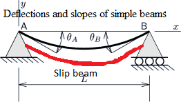
It should slide.
Simulate requires constraints on his feet.
Sincerely.
Denis

- Mark as New
- Bookmark
- Subscribe
- Mute
- Subscribe to RSS Feed
- Permalink
- Notify Moderator
Denis, can you describe what you are trying to model? Do you have a picture of the real parts maybe? That could help a great deal.
- Mark as New
- Bookmark
- Subscribe
- Mute
- Subscribe to RSS Feed
- Permalink
- Notify Moderator
Hi Denis,
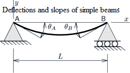
Although the thread title says "two simple supports", in the diagram you show (which is the classic diagram for a simply-supported beam) the constraints are different at each end.
The left-hand end is constrained in Tx and Ty (and in 3D, Tz as well).
The right-hand end is constrained in Ty (and Tz) but is free in Tx.
If you create these constraints in your model, does it give the answer you are looking for?
- Mark as New
- Bookmark
- Subscribe
- Mute
- Subscribe to RSS Feed
- Permalink
- Notify Moderator
Hello,
Thank you for your very specific answers.
Actually I have not chosen the right design for my question.
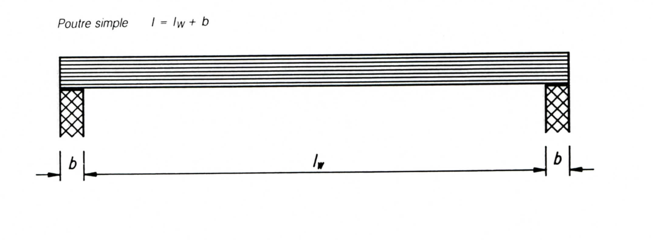
It is a simply supported beam laid plans without restraint.
See the attached drawing.
Sincerely.
Denis.

- Mark as New
- Bookmark
- Subscribe
- Mute
- Subscribe to RSS Feed
- Permalink
- Notify Moderator
The same constraints would be appropriate, even so.
To ensure 'necessary and sufficient' constraint, we assume that one end will slide and the other end will remain fixed.
- Mark as New
- Bookmark
- Subscribe
- Mute
- Subscribe to RSS Feed
- Permalink
- Notify Moderator
Yes thank you.
That's how I always do.
I thought it could be another solution.


