
Turn on suggestions
Auto-suggest helps you quickly narrow down your search results by suggesting possible matches as you type.
Showing results for
Please log in to access translation
Turn on suggestions
Auto-suggest helps you quickly narrow down your search results by suggesting possible matches as you type.
Showing results for
Community Tip - You can subscribe to a forum, label or individual post and receive email notifications when someone posts a new topic or reply. Learn more! X
- Community
- Creo+ and Creo Parametric
- Analysis
- Re: Structural results evaluation: deformed displa...
Translate the entire conversation x
Please log in to access translation
Options
- Subscribe to RSS Feed
- Mark Topic as New
- Mark Topic as Read
- Float this Topic for Current User
- Bookmark
- Subscribe
- Mute
- Printer Friendly Page
Structural results evaluation: deformed display scaling percentage meaning
Jun 19, 2015
08:33 AM
- Mark as New
- Bookmark
- Subscribe
- Mute
- Subscribe to RSS Feed
- Permalink
- Notify Moderator
Please log in to access translation
Jun 19, 2015
08:33 AM
Structural results evaluation: deformed display scaling percentage meaning
Hallo,
anyone could be able to explain what is the mathematical law which stands behind the Scaling option and its percentage value ?
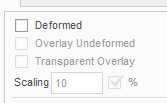
for example: 10 % means that deformed displacement values are 100+10 % = 110% of the real values (that is 10 % bigger) ?
also, which result values get increased by setting this option? are they the absolute displacements of each point?
thanks
Bye
This thread is inactive and closed by the PTC Community Management Team. If you would like to provide a reply and re-open this thread, please notify the moderator and reference the thread. You may also use "Start a topic" button to ask a new question. Please be sure to include what version of the PTC product you are using so another community member knowledgeable about your version may be able to assist.
Labels:
- Labels:
-
Simulate
6 REPLIES 6
Jun 19, 2015
09:09 AM
- Mark as New
- Bookmark
- Subscribe
- Mute
- Subscribe to RSS Feed
- Permalink
- Notify Moderator
Please log in to access translation
Jun 19, 2015
09:09 AM
You can do your own testing, but I just ran a study on a 1x1x.25 thick part. I fixed one end and I added an applied displacement (.25) to the other end.
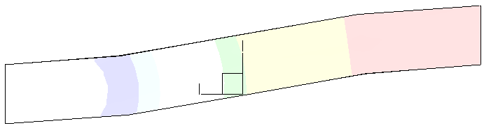
Looking at a side view it appeared that 25% scaling made for 100% real life scaling (ie I expected that the displaced bottom edge lined up with the fixed top edge on the opposite surface. I then changed the applied displacement to .125. This time though when 25% scaling the displayed result was the same which isn't what I expected. at 25% scaling for a .125" displacement the displaced bottom edge lined up with the fixed top edge of the opposite surface as before. I would have expected it to be half my first result because the applied displacement was half.
That being said it appears that the scaling is based off of a bounding part size and not the magnitude of the displacement results. To further affirm this, I changed the thickness to .125 and sure enough now a scaling of 12.5% makes the bottom displaced surface line up with the top of the fixed edge surface. Picture below is for the last case of .125 thick with a scaling factor of 12.5%.
Jun 20, 2015
04:32 AM
- Mark as New
- Bookmark
- Subscribe
- Mute
- Subscribe to RSS Feed
- Permalink
- Notify Moderator
Please log in to access translation
Jun 20, 2015
04:32 AM
Hi,
The scaling 10% is the default for a study without contact.
The largest displacement in the model is scaled to be 10% of the 'model size'.
All other displacements are scaled accordingly

For contact solutions, the default scale is 1 (absolute, and not %). This is because the movement when taking up a contact gap or 2 contacting surfaces sliding relative to each other can be significantly greater than the largest displacement due to bending and stretching material. Viewing contact results with 10% would cause the movement at the contact to be scaled to 10% of model size potentially swamping the info required.
It is possible to switch between absolute and % for either contact or non-contact results.
Regards
Jun 22, 2015
04:43 AM
- Mark as New
- Bookmark
- Subscribe
- Mute
- Subscribe to RSS Feed
- Permalink
- Notify Moderator
Please log in to access translation
Jun 22, 2015
04:43 AM
Just to add to Charles' description, my understanding is that the 'percentage' option is good for checking the general deformed shape of a part - applying "10%" deformation always gives a deformed shape that allows you to visually check that the model is behaving in the way you expect, regardless of the absolute values.
Once you've checked that the shape looks correct, obviously the next thing should be to check that the values look correct (assuming that you haven't already done this by looking at the run status files!).
Jun 22, 2015
05:19 AM
- Mark as New
- Bookmark
- Subscribe
- Mute
- Subscribe to RSS Feed
- Permalink
- Notify Moderator
Please log in to access translation
Jun 22, 2015
05:19 AM
Thanks to all of you for your replies, they were all extremely useful.
In particular, it seems I can now explain a strange behaviour (that was also one of the reasons why I opened the topic) that I was having with contact analysis results: when I set for example 10% it often happens that two contacting surfaces interpenetrate each other (thing that would be impossible)--> so this is because the gap is amplified? also even if the initial gap is zero? (conincident contacting surfaces)
thanks
bye
Jun 22, 2015
05:28 AM
- Mark as New
- Bookmark
- Subscribe
- Mute
- Subscribe to RSS Feed
- Permalink
- Notify Moderator
Please log in to access translation
Jun 22, 2015
05:28 AM
Hi Tommaso,
The gap is not amplified, but the displacements are.
If there is an initial gap and it is closed during the analysis, then any displacement scaling larger than 1.0 will show interpenetration - for example, if the gap is 1mm then one surface must displace by 1mm to close it, but if you apply a scaling factor of 2 then the surface will appear to move by 2mm, giving 1mm of interpenetration.
Note that regardless of whether you apply "50" or "10%", the scaling factor shown in the upper left of the results window is still absolute - you can see what scale factor has really been applied.
If there is exactly zero initial gap, then you should not see interpenetration other than through accuracy issues. If the surfaces separate, then the gap shown will be scaled by the scaling factor.
Jul 01, 2015
10:44 AM
- Mark as New
- Bookmark
- Subscribe
- Mute
- Subscribe to RSS Feed
- Permalink
- Notify Moderator
Please log in to access translation
Jul 01, 2015
10:44 AM
Thanks for all of your replies!
bye
Announcements


Top Tags
