cancel
Showing results for 
Search instead for 
Did you mean: 
cancel
Showing results for 
Search instead for 
Did you mean: 

Community Tip - You can subscribe to a forum, label or individual post and receive email notifications when someone posts a new topic or reply. Learn more! X

large gears are always incorrect and interfere?

bp
6-Contributor
6-Contributor

large gears are always incorrect and interfere?

For a new project Im going to waterjet cut two large metric spur gears (no I will not simply buy them).

The center distance will be (module 3 x 60 teeth) =180 mm (= both nominal diameters/2).

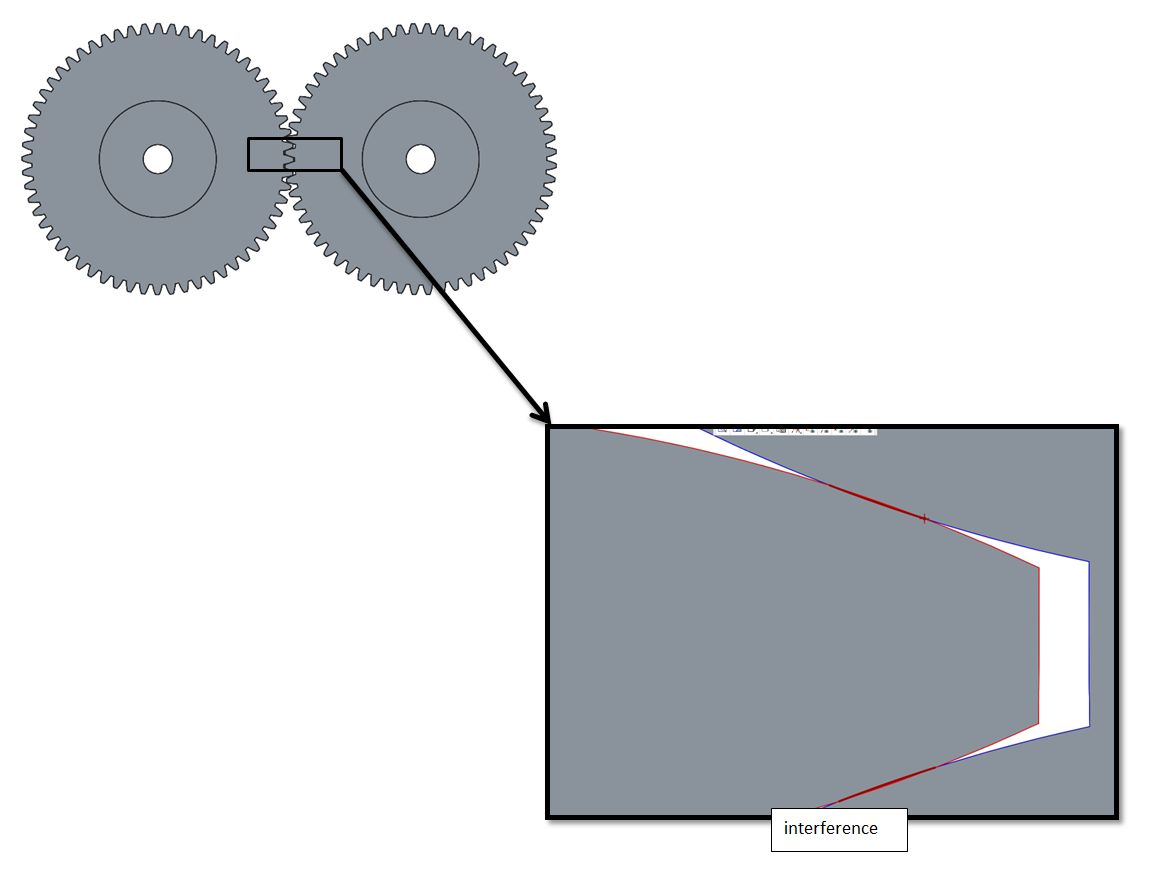
In Creo I've found out that these gears will actually interfere, See image .

Surely real gears dont have this problem, but since Im going to cut them myself, I will actually have this problem.

So whats going on? It doesnt matter whether I download a 3d model of a gear from a manufacturer or create a parametric spur gear myself (both using standard formulas), the interference is there.

How do I solve this? Should I create a cut on the spurgear (a small offset) to avoid interference? But then the contact point is not optimal anymore?

Any ideas?

spurgear.jpg


This thread is inactive and closed by the PTC Community Management Team. If you would like to provide a reply and re-open this thread, please notify the moderator and reference the thread. You may also use "Start a topic" button to ask a new question. Please be sure to include what version of the PTC product you are using so another community member knowledgeable about your version may be able to assist.
1 ACCEPTED SOLUTION

Accepted Solutions

I picked up some of my old gears that I created the geometry from scratch.

They do not show an overlap at all when properly meshed.

gear_mesh.PNG

This is the involute equation used:

r=d4

ang=t*90

s=(pi*r*t)/2

xc=r*cos(ang)
yc=r*sin(ang)

x=xc+(s*sin(ang))
y=yc-(s*cos(ang))
z=0

Feel free to run your interference analysis and see what it comes up with.

Graphically, it looks fine.

View solution in original post

3 REPLIES 3
TomD.inPDX
17-Peridot
(To:bp)

Creo has some very course approximation dependent on part accuracy. These are very prominent in equations like involutes. There are also areas where you may input a formula but the data entered is only the accuracy of your current number of digits. All are correctable, but you have to be aware of them. So far, I've had pretty accurate results.

Although the formula available provide a perfect interface, you must also account for the deviation tolerance. The formula should therefore represent a maximum material condition. Once you have the "perfect" shape, offset the face to the allowable backlash you can tolerate. Then mirror and pattern that feature.

Depending on how you plan to mount the gears, you can always have some adjustment for backlash. You will be amazed at how forgiving a gearset will be unless you really push the structural limits.

Depending on your application, you could just increase the centre distance slightly to add some backlash.

A 'standard' centre distance in many motorsport gearboxes is 102.6 mm - which, I'm told, originated as "4 inches (nominal design value) plus 1 mm for backlash"! If that's true, that amount wouldn't be too far off for 3 module gears - most of our gears are circa 3.5-4.2 module, and we typically specify 0.1-0.2 mm of backlash (circumferential rather than normal, I think).

I picked up some of my old gears that I created the geometry from scratch.

They do not show an overlap at all when properly meshed.

gear_mesh.PNG

This is the involute equation used:

r=d4

ang=t*90

s=(pi*r*t)/2

xc=r*cos(ang)
yc=r*sin(ang)

x=xc+(s*sin(ang))
y=yc-(s*cos(ang))
z=0

Feel free to run your interference analysis and see what it comes up with.

Graphically, it looks fine.

Top Tags