Community Tip - Visit the PTCooler (the community lounge) to get to know your fellow community members and check out some of Dale's Friday Humor posts! X
- Community
- Creo (Previous to May 2018)
- Creo Modeling Questions
- Re: Center of Gravity Icon?
- Subscribe to RSS Feed
- Mark Topic as New
- Mark Topic as Read
- Float this Topic for Current User
- Bookmark
- Subscribe
- Mute
- Printer Friendly Page
Center of Gravity Icon?
- Mark as New
- Bookmark
- Subscribe
- Mute
- Subscribe to RSS Feed
- Permalink
- Notify Moderator
Center of Gravity Icon?
I wondering if someone can help me with a simple way to display the CG of a model. I know in the past I have seen models that had a small sphere at the CG, but I have no idea how they placed it.
Solved! Go to Solution.
Accepted Solutions
- Mark as New
- Bookmark
- Subscribe
- Mute
- Subscribe to RSS Feed
- Permalink
- Notify Moderator
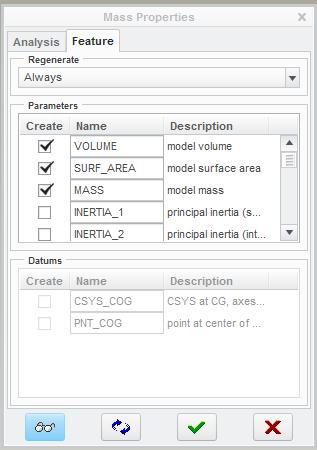
The easy way.....If you have the right module create a mass properties feature (See attached image) and you can check the create point at COG option at the bottom (Mine is greyed out because we don't have that module.)

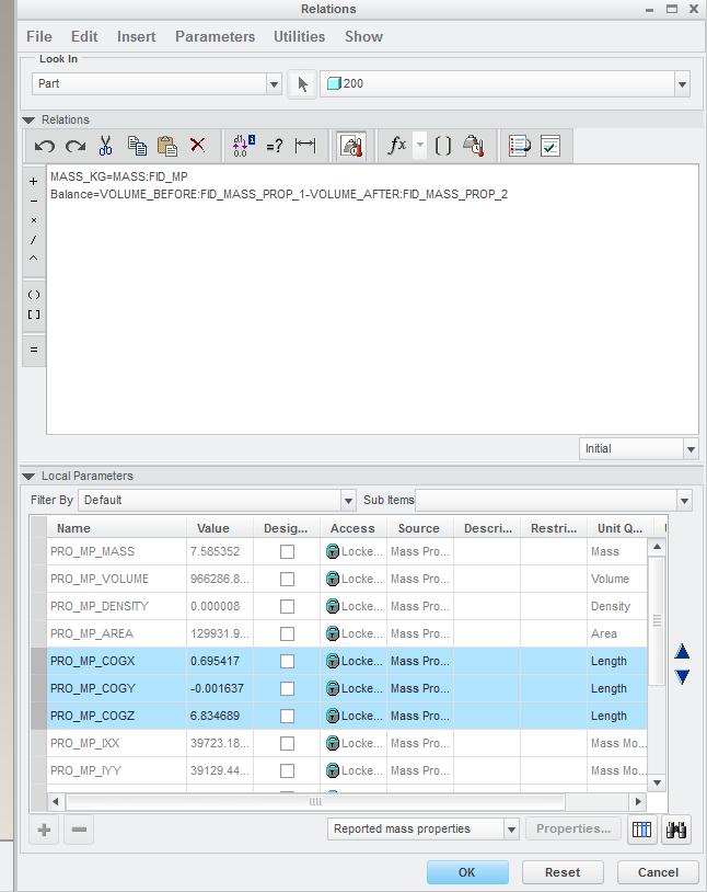
The more difficult way....You could probably write some relations that take info from the mass properties parameters and use them to drive the location of your COG point. See image below. That means your point will stay at the COG as the model changes. Then model a surface sphere as suggested at the point.

- Mark as New
- Bookmark
- Subscribe
- Mute
- Subscribe to RSS Feed
- Permalink
- Notify Moderator
It's an old school method....
Run a mass props and find record the X,Y and Z coordinates. Add a Datum Point at that location, create a revolved surface sphere as large as you like. Add some vector arrows if you wish. I like the sphere method because I can see it from any view orientation.
If you change your model, just rerun the mass and edit your point's coordinates and the sphere will follow.
- Mark as New
- Bookmark
- Subscribe
- Mute
- Subscribe to RSS Feed
- Permalink
- Notify Moderator
Thanks for the response,
The issue I have with that method is that if the CG changes the sphere won't move. I'm wondering of there is a way to place an indicator that moves with the CG as items are added or removed from an assembly.
- Mark as New
- Bookmark
- Subscribe
- Mute
- Subscribe to RSS Feed
- Permalink
- Notify Moderator
If you change the analysis to "Feature" you can then have it create a dynamic point that will move.
In Creo the steps are: Analaysis -> Mass Properties -> Change the drop down to "Feature". Click on the Feature tab and then check Create point (you can also create a CYS)
After this you can attach anything you want to that point
- Mark as New
- Bookmark
- Subscribe
- Mute
- Subscribe to RSS Feed
- Permalink
- Notify Moderator
How do I get it to create a dynamic point?
- Mark as New
- Bookmark
- Subscribe
- Mute
- Subscribe to RSS Feed
- Permalink
- Notify Moderator
The easy way.....If you have the right module create a mass properties feature (See attached image) and you can check the create point at COG option at the bottom (Mine is greyed out because we don't have that module.)

The more difficult way....You could probably write some relations that take info from the mass properties parameters and use them to drive the location of your COG point. See image below. That means your point will stay at the COG as the model changes. Then model a surface sphere as suggested at the point.

- Mark as New
- Bookmark
- Subscribe
- Mute
- Subscribe to RSS Feed
- Permalink
- Notify Moderator
Looks like I don't have the correct module either, mine is greyed out as well. That explains why I haven't been able to find an easy way to do this.
- Mark as New
- Bookmark
- Subscribe
- Mute
- Subscribe to RSS Feed
- Permalink
- Notify Moderator
I couldn't remember the exact steps so I did a quick search and found this:
1. If you don't already have one, create a default coordinate
system in the part.
2. Calculate part mass properties.
3. Create a datum point offset from the coordinate system with dimensions. Specify the coordinate system as Cartesian. Enter any arbitrary x, y, and z values.
4. Create relations to drive the datum point's three translation
dimensions as follows:
$d#=mp_cg_x("","coord_sys","") X Translation
$d#=mp_cg_y("","coord_sys","") Y Translation
$d#=mp_cg_z("","coord_sys","") Z Translation
The $ HAS to be in front.
d# is the dimension number, for assemblies, this will be d#:#.
Coord_sys is the name of the coordinate system the point is offset from(i.e., for parts: CSYS_PART_DEF, for assemblies: CSYS_ASM_DEF).
5. Regenerate the part.
6. Mass properties need to be recalculated after a part change,
then the part needs to be regenerated to update the relations.
Steps 5 and 6 need to be repeated after any change to the model
geometry.
- Mark as New
- Bookmark
- Subscribe
- Mute
- Subscribe to RSS Feed
- Permalink
- Notify Moderator
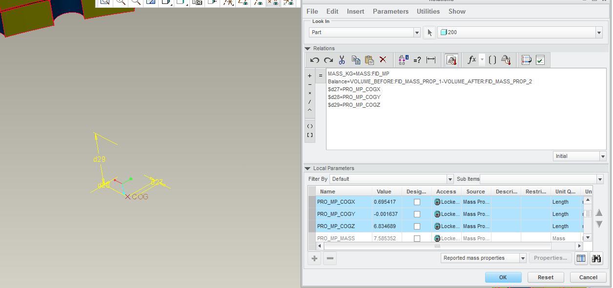
I just tried it out but I see Stephen Williams beat me to it. Works perfectly. These were my relations. If you want to sketch the sphere then you will have to create a plane through the point to sketch on.

- Mark as New
- Bookmark
- Subscribe
- Mute
- Subscribe to RSS Feed
- Permalink
- Notify Moderator
It may also be grayed out because you didn't change the drop down from "Quick" To "Feature"
- Mark as New
- Bookmark
- Subscribe
- Mute
- Subscribe to RSS Feed
- Permalink
- Notify Moderator
Thanks for the replies everyone, I appreciate the help.

