
Turn on suggestions
Auto-suggest helps you quickly narrow down your search results by suggesting possible matches as you type.
Showing results for
Please log in to access translation
Turn on suggestions
Auto-suggest helps you quickly narrow down your search results by suggesting possible matches as you type.
Showing results for
Community Tip - Your Friends List is a way to easily have access to the community members that you interact with the most! X
- Community
- Creo (Previous to May 2018)
- Creo Modeling Questions
- Re: Equation curve / sketch projection accuracy
Translate the entire conversation x
Please log in to access translation
Options
- Subscribe to RSS Feed
- Mark Topic as New
- Mark Topic as Read
- Float this Topic for Current User
- Bookmark
- Subscribe
- Mute
- Printer Friendly Page
Equation curve / sketch projection accuracy
Mar 27, 2017
07:34 AM
- Mark as New
- Bookmark
- Subscribe
- Mute
- Subscribe to RSS Feed
- Permalink
- Notify Moderator
Please log in to access translation
Mar 27, 2017
07:34 AM
Equation curve / sketch projection accuracy
Hi all,
I've got a pair of components in which we've modelled an involute spline explicitly, using an equation curve.
The modelling approach is as follows:
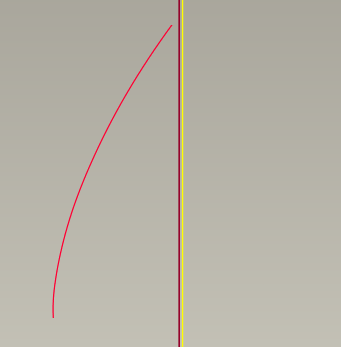
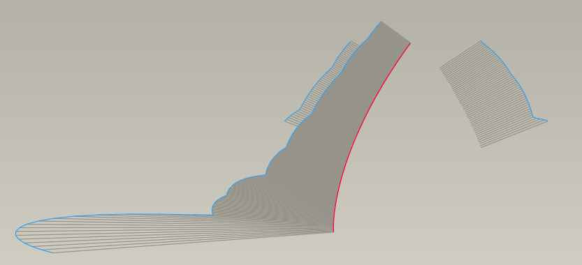
Generate one involute curve from the base circle up to a diameter beyond the final tip diameter:
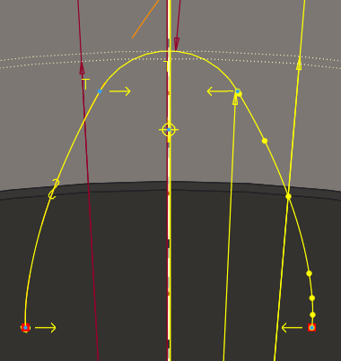
Extrude this, by Projecting it into a sketch, mirroring it, and adding a root fillet between the two flanks:
The involute equation includes an offset angle, which generates the clearance between the two parts by effectively rotating the offset about the origin. If I measure the angle between the two curves at any diameter, I get a constant angle, as I expect:
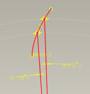
However, when I measure between the actual solid geometry (and this is what our analyst noticed when running FEA), the angle is not constant, and the OD is closer than the ID:
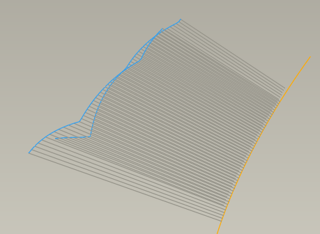
It appears to affect both flanks, regardless of whether it's the 'original' or mirrored side, so I don't think it's caused by the mirroring op. A curvature analysis also suggests that the mirror is good, although it does show some worrying unevenness:
Is this an accuracy issue? I've tried tightening the accuracy (absolute) but without fixing the problem. Has anyone else experienced anything similar?
Thanks!
5 REPLIES 5
Mar 27, 2017
08:35 AM
- Mark as New
- Bookmark
- Subscribe
- Mute
- Subscribe to RSS Feed
- Permalink
- Notify Moderator
Please log in to access translation
Mar 27, 2017
08:35 AM
Also, the curvature for the two parts doesn't seem to match:
Mar 28, 2017
06:12 AM
- Mark as New
- Bookmark
- Subscribe
- Mute
- Subscribe to RSS Feed
- Permalink
- Notify Moderator
Please log in to access translation
Mar 28, 2017
06:12 AM
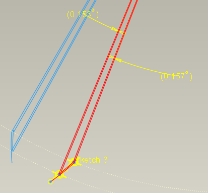
In Creo 3 (M120), I compare an involute generated using the "curve from equation" (labelled with blue leader lines)
to the same-sized involute generated by spline->from file sketching tool with the 90 points in the file calculated using the same formula but in an excel worksheet (light green)
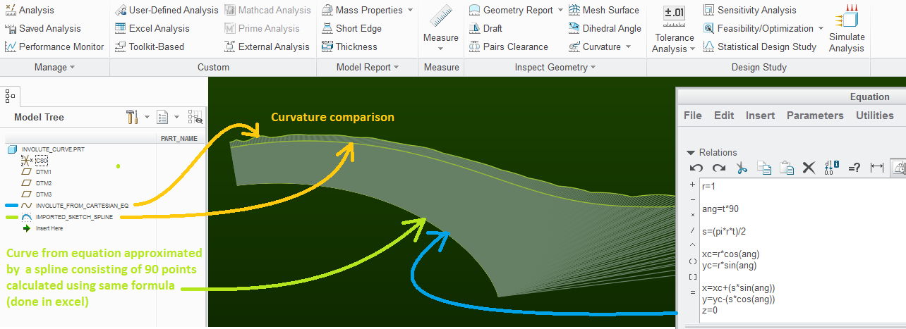
visually, the two involutes overlap - but the curvature analysis reveals that there is something fishy about these curves from equations - their curvature graph should be smooth.
Mar 28, 2017
06:51 AM
- Mark as New
- Bookmark
- Subscribe
- Mute
- Subscribe to RSS Feed
- Permalink
- Notify Moderator
Please log in to access translation
Mar 28, 2017
06:51 AM
I suspect, following further discussion with a colleague, that the curvature is suffering from the transformation from equation to NURBS - and your model suggests that there are probably accuracy / interpolation / rounding / evaluation issues with the equation curves too. That I can, to some extent, accept; but the larger-scale discrepancy in position is more of a problem to me right now.
Anyway, I've got a call actively under investigation, so we'll see what's reported.
Mar 28, 2017
09:33 AM
- Mark as New
- Bookmark
- Subscribe
- Mute
- Subscribe to RSS Feed
- Permalink
- Notify Moderator
Please log in to access translation
Mar 28, 2017
09:33 AM
It appears to have been the mirror in one of the sketches, which for some reason had not updated or had become detached from the source geometry.
Well found, that PTC tech!
Mar 28, 2017
10:41 AM
- Mark as New
- Bookmark
- Subscribe
- Mute
- Subscribe to RSS Feed
- Permalink
- Notify Moderator
Please log in to access translation
Mar 28, 2017
10:41 AM
any time you copy geometry in a sketch that is not explicitly an analytical curve (e.g. arc, circle, or line, or conic(sometimes) ) it will become a spline. a 3rd degree spline that is matched by tolerance to the curve. this is why the ugly curvature plot. IMO it'd be better if they would match using 5th degree curves, but oh well.
The same thing happens from ISDX curves (style) if you use edge in a sketch they go from being gorgeously smooth curves to pretty much hideous looking curvature plots *** that said, the error is mathematical - so most situations it doesn't really matter. You might say "it'll show in the reflections"... I'd say probably not on anything small. Truth is, that error will lost in the noise of production in most cases.
the big error was the real issue and sounds like you've got that sorted.
if you mirror a feature (the curve from equation) then it can, unless you are careful, create an un-connected copy of the feature that is then mirrored.
I usually like to mirror geometry rather than features, because, to me, it seems more intuitive and direct and doesn't create features with unintuitive paths to edit.
select the curve geometry, and then click mirror, select the mirror plane and click ok. this creates a mirror of the geometry that will ALWAYS update to the geometry you selected and is redefinable/reroutable. so it is more often more easily repaired if things break.
I'm not saying I never mirror features, just saying that I do it less often than selected geometry.
e.g. for symmetrical parts, I actually create a copy surface, then mirror that feature, then delete the original copy. again - it's for robustness of repair later if things mess up.
