- Community
- Creo (Previous to May 2018)
- Creo Modeling Questions
- HOW TO CREATE MODEL OF WIRE ROPE
- Subscribe to RSS Feed
- Mark Topic as New
- Mark Topic as Read
- Float this Topic for Current User
- Bookmark
- Subscribe
- Mute
- Printer Friendly Page
HOW TO CREATE MODEL OF WIRE ROPE
- Mark as New
- Bookmark
- Subscribe
- Mute
- Subscribe to RSS Feed
- Permalink
- Notify Moderator
HOW TO CREATE MODEL OF WIRE ROPE
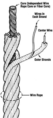
I WANT TO DESIGNE A MODEL OF WIRE ROPE WITH A SPECIFIC DIAMENTION PLEAS HELP ME FOR THIS
- Mark as New
- Bookmark
- Subscribe
- Mute
- Subscribe to RSS Feed
- Permalink
- Notify Moderator
This should be what you are after:
- Mark as New
- Bookmark
- Subscribe
- Mute
- Subscribe to RSS Feed
- Permalink
- Notify Moderator
- Mark as New
- Bookmark
- Subscribe
- Mute
- Subscribe to RSS Feed
- Permalink
- Notify Moderator
This was really help full for me but there are several difficulties in my model VSS cant helpfull for me can you please explane it in detail......
- Mark as New
- Bookmark
- Subscribe
- Mute
- Subscribe to RSS Feed
- Permalink
- Notify Moderator
Using the variable section sweep is something that takes practice. This is definitely an advanced function.
This also requires significant computing power. Technique is important for the models to remain interactive.
You really want to be conscious about your geometry. Do your homework on the actual geometry before you begin making the part. You have to know how to use curves and joint them to make the sweeps if you are after the diagram in your original post.
I also recommend using an assembly to add the elements together.
Normally, details to this degree are ignored in CAD such as Creo. We make a tube and give it a cable texture and all is good. But all to often a marketing type will think it nice to have a real "thing" made in CAD when they have no idea just what they are asking.
Many of the participants in the forum know how to get these results, but it is not simple lesson. It is at least 4 levels comprehension of the software and defining cable in general.
- Mark as New
- Bookmark
- Subscribe
- Mute
- Subscribe to RSS Feed
- Permalink
- Notify Moderator
- Mark as New
- Bookmark
- Subscribe
- Mute
- Subscribe to RSS Feed
- Permalink
- Notify Moderator
kind of neat, but I don't have time to continue at the moment.
- Mark as New
- Bookmark
- Subscribe
- Mute
- Subscribe to RSS Feed
- Permalink
- Notify Moderator
Remember to use "normal to trajectory" on those wires to keep them "round".
- Mark as New
- Bookmark
- Subscribe
- Mute
- Subscribe to RSS Feed
- Permalink
- Notify Moderator
please help me to complete this your model this model exactly same as i want please...
thanks for your valuable time...... i hope you will help me for this
- this is my email id you can contact me on this........
- Mark as New
- Bookmark
- Subscribe
- Mute
- Subscribe to RSS Feed
- Permalink
- Notify Moderator
It fails trying to make another sweep, I'm not sure why at the moment.
- Mark as New
- Bookmark
- Subscribe
- Mute
- Subscribe to RSS Feed
- Permalink
- Notify Moderator
I have found in similar constructions that significant amounts of changing part accuracy were needed. It wasn't predictable. Make the part even a little different either way and a different accuracy number was required.
- Mark as New
- Bookmark
- Subscribe
- Mute
- Subscribe to RSS Feed
- Permalink
- Notify Moderator
There is a lot of calculations going on with near or perfect tangency and this confuses the software. It is much better to assemble such an object than to make it a single part file.
- Mark as New
- Bookmark
- Subscribe
- Mute
- Subscribe to RSS Feed
- Permalink
- Notify Moderator
Centre wire dia.3.94mm;
outer wire dia.3.73mm
strand height-115mm;
pitch length-115mm and
helix angle 78.2 degree
This is an dimensions of wire rope which I want to design
In pro-E wf5 as assembly model
Please help for this
- Mark as New
- Bookmark
- Subscribe
- Mute
- Subscribe to RSS Feed
- Permalink
- Notify Moderator
The part I was working with was a single non-self intersecting VSS protrusion along a datum curve. It was practice to make an animation. I wrote a trail file generator that would increment to make a protrusion that looped around. It would generate a few frames, then crash on geometry fail. Change the accuracy up or down and it would run a few more and then crash again.
As far as this case it concerned, I'd say modeling a wire rope is interesting as an excercise, but a waste of design time. There is no analytical value. If there is something to be known, the wire rope makers know it already.
If it is homework, it's for the student to do.
The design is completely descibed by the section and twist rate(s), so the conceptual design is done.
- Mark as New
- Bookmark
- Subscribe
- Mute
- Subscribe to RSS Feed
- Permalink
- Notify Moderator
Matt Griswold i am useing Pro-E wf 5 in this your model or prt file doesnot open....
so plz help me to open it...
I am very thankful to u for your valuable reply....
- Mark as New
- Bookmark
- Subscribe
- Mute
- Subscribe to RSS Feed
- Permalink
- Notify Moderator
Yes I am using Creo2. I don't have WF5 installed.
- Mark as New
- Bookmark
- Subscribe
- Mute
- Subscribe to RSS Feed
- Permalink
- Notify Moderator
Can any method to open creo 2.0 prt file into pro E wf 5
- Mark as New
- Bookmark
- Subscribe
- Mute
- Subscribe to RSS Feed
- Permalink
- Notify Moderator
How far have you gotten with it? Have any pics?
- Mark as New
- Bookmark
- Subscribe
- Mute
- Subscribe to RSS Feed
- Permalink
- Notify Moderator
This Error is showing when i am opening the prt file which is given below...
- Mark as New
- Bookmark
- Subscribe
- Mute
- Subscribe to RSS Feed
- Permalink
- Notify Moderator
yeah it's a Creo2 file. I meant how far have you gotten with drawing your wire rope.
- Mark as New
- Bookmark
- Subscribe
- Mute
- Subscribe to RSS Feed
- Permalink
- Notify Moderator
- Mark as New
- Bookmark
- Subscribe
- Mute
- Subscribe to RSS Feed
- Permalink
- Notify Moderator
looks good so far.
- Mark as New
- Bookmark
- Subscribe
- Mute
- Subscribe to RSS Feed
- Permalink
- Notify Moderator
- Mark as New
- Bookmark
- Subscribe
- Mute
- Subscribe to RSS Feed
- Permalink
- Notify Moderator
You are getting there ![]()
- Mark as New
- Bookmark
- Subscribe
- Mute
- Subscribe to RSS Feed
- Permalink
- Notify Moderator
Yaa but main problem is there how to create the other wires which is helix to the curve wire please any one help me for this.... I am using pro-e wf5
- Mark as New
- Bookmark
- Subscribe
- Mute
- Subscribe to RSS Feed
- Permalink
- Notify Moderator
See http://communities.ptc.com/message/154713#154713.
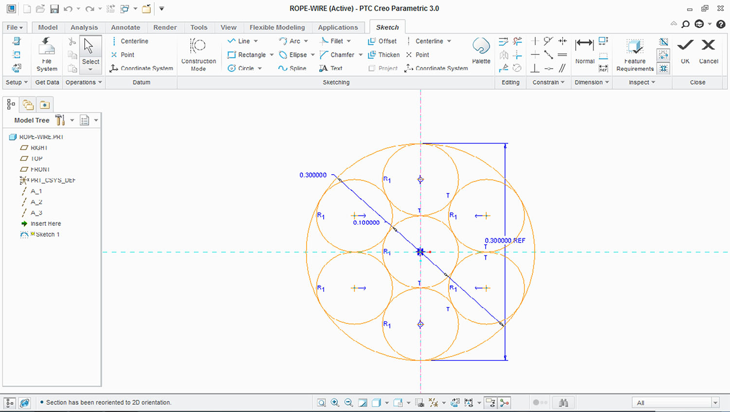
Create the core wire datum curve so that it spirals and then create a second datum curve with a larger radius to use as the x-direction reference for use as a basis for a variable section sweep to model the wires that twist around the spiral curve. The spiral curve can be used for a regular sweep.
You'll need to use trajpar() in a relation to drive the rate of twist of the secondary wires around the primary wire datum curve.
- Mark as New
- Bookmark
- Subscribe
- Mute
- Subscribe to RSS Feed
- Permalink
- Notify Moderator
Please any one help me for this model I can't understand trajpar() relation or VSS can any one send me the picture of this relation which can b only for 6 helical wires around the one curve.
Thank you for helping me....
- Mark as New
- Bookmark
- Subscribe
- Mute
- Subscribe to RSS Feed
- Permalink
- Notify Moderator
- Mark as New
- Bookmark
- Subscribe
- Mute
- Subscribe to RSS Feed
- Permalink
- Notify Moderator
The link I provided before details this exactly:
- Mark as New
- Bookmark
- Subscribe
- Mute
- Subscribe to RSS Feed
- Permalink
- Notify Moderator
can you define the relation between rope and wires, any video tutorial?

