
Turn on suggestions
Auto-suggest helps you quickly narrow down your search results by suggesting possible matches as you type.
Showing results for
Please log in to access translation
Turn on suggestions
Auto-suggest helps you quickly narrow down your search results by suggesting possible matches as you type.
Showing results for
Community Tip - If community subscription notifications are filling up your inbox you can set up a daily digest and get all your notifications in a single email. X
- Community
- Creo (Previous to May 2018)
- Creo Modeling Questions
- Turnbuckle with symmetric slider constraint
Translate the entire conversation x
Please log in to access translation
Options
- Subscribe to RSS Feed
- Mark Topic as New
- Mark Topic as Read
- Float this Topic for Current User
- Bookmark
- Subscribe
- Mute
- Printer Friendly Page
Turnbuckle with symmetric slider constraint
Feb 06, 2015
10:05 AM
- Mark as New
- Bookmark
- Subscribe
- Mute
- Subscribe to RSS Feed
- Permalink
- Notify Moderator
Please log in to access translation
Feb 06, 2015
10:05 AM
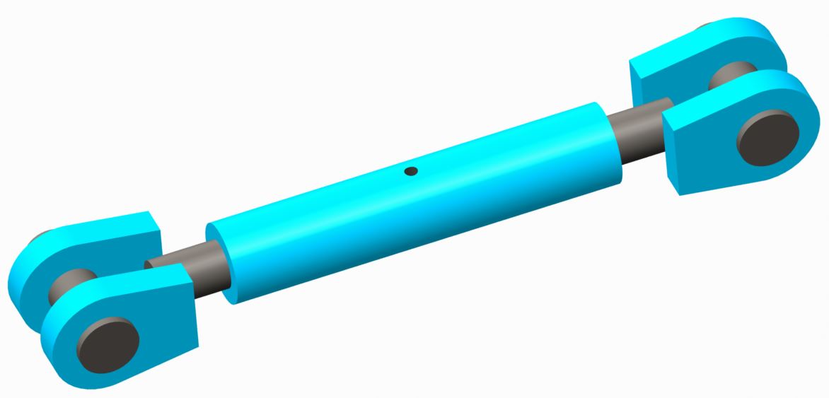
Turnbuckle with symmetric slider constraint
Hi,
I have assembled a turnbuckle and I have placed the two spindles with 'slider' constraints. However, I would like both spindles to move symmetrically related to the body of the turnbuckle when one spindle is dragged. I thought that it was possible to create a relation that would make the distance from the body of the turnbuckle to the spindle half of the extension.
Does anyone have experience with this?
Regards
Niels
11 REPLIES 11
Feb 06, 2015
03:11 PM
- Mark as New
- Bookmark
- Subscribe
- Mute
- Subscribe to RSS Feed
- Permalink
- Notify Moderator
Please log in to access translation
Feb 06, 2015
03:11 PM
2 helical sweeps, one left-hand, one right-hand, with cylinder and planar constraints on the center, and slider and slot constraints on the ends.
Feb 06, 2015
11:00 PM
- Mark as New
- Bookmark
- Subscribe
- Mute
- Subscribe to RSS Feed
- Permalink
- Notify Moderator
Please log in to access translation
Feb 06, 2015
11:00 PM
Rack and pinion gear relation in mechanism.
Feb 09, 2015
09:37 AM
- Mark as New
- Bookmark
- Subscribe
- Mute
- Subscribe to RSS Feed
- Permalink
- Notify Moderator
Please log in to access translation
Feb 09, 2015
09:37 AM
That would work, but then the turnbuckle center wouldn't turn, would it? Mybe I'm trying to be too fancy..... 
Feb 09, 2015
09:48 AM
- Mark as New
- Bookmark
- Subscribe
- Mute
- Subscribe to RSS Feed
- Permalink
- Notify Moderator
Please log in to access translation
Feb 09, 2015
09:48 AM
I have converted it to a flexible component in the assembly in which it is used. Then I have introduced a relation that makes the distance from the centre of the pin to the centre of the body half of the pin-to-pin distance. This works to some extent, but constraining it in the upper level assembly is still a bit tricky.
....you can never make it too fancy. However, project managers do not appreciate creativity so sometimes we need to stop early if we don't want to listen to their whining.
Feb 09, 2015
11:34 AM
- Mark as New
- Bookmark
- Subscribe
- Mute
- Subscribe to RSS Feed
- Permalink
- Notify Moderator
Please log in to access translation
Feb 09, 2015
11:34 AM
That works too, I guess I just (maybe incorrectly) assumed you'd meant that you wanted to be able to turn the turnbuckle and have the ends come in. And I TOTALLY agree on the managers having any sense of what we actually do. You can be the best, most valuable CAD wizard on the planet, and you will never get any respect for it. In their minds, you're just a glorified "drafter".......
Feb 09, 2015
12:37 PM
- Mark as New
- Bookmark
- Subscribe
- Mute
- Subscribe to RSS Feed
- Permalink
- Notify Moderator
Please log in to access translation
Feb 09, 2015
12:37 PM
If you leave the link unconstrained as a cylinder, you should be able to constrain the holes at both ends at the next level.
You can also apply some relations to the turn-buckle to set the span in the higher level assembly. The relation can be associated to a measure feature, for instance.
I'd have to do it to give more info, but it is a fairly straight forward process. Learn it once and save a reference model for later.
Feb 10, 2015
02:10 AM
- Mark as New
- Bookmark
- Subscribe
- Mute
- Subscribe to RSS Feed
- Permalink
- Notify Moderator
Please log in to access translation
Feb 10, 2015
02:10 AM
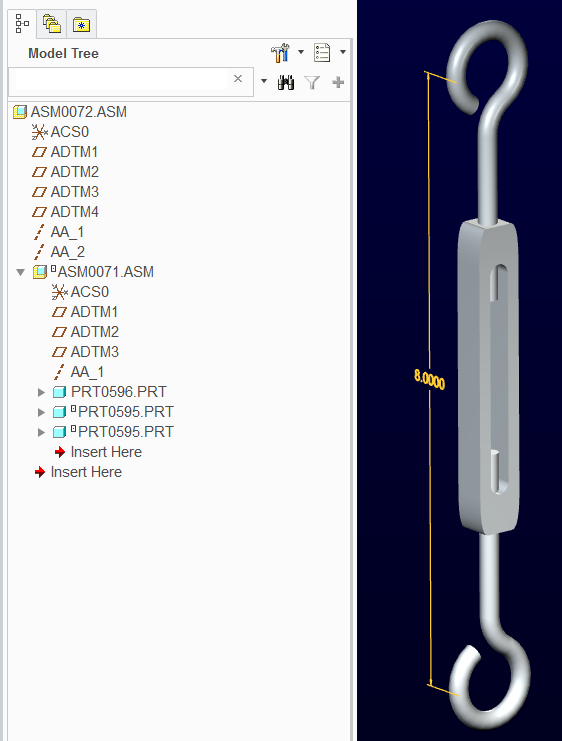
Fairly straight forward.
The ends are assembled as cylinder connections. Do not apply regen values.
The turnbuckle assembly has a relation for the distance of one to the other.
This remains variable but equal.
The next level assembly has the axes for setting the distance.
In this case, changing datum 4 location also changes the strut length after the 1st regen.
To get the green light, you have to do one additional regen.
Creo 2.0 attached
Feb 09, 2015
11:38 AM
- Mark as New
- Bookmark
- Subscribe
- Mute
- Subscribe to RSS Feed
- Permalink
- Notify Moderator
Please log in to access translation
Feb 09, 2015
11:38 AM
You could use a slot and follower connection. It uses a curve to determine the movement of a point. Just create a helical curve on the surface of the "threaded" shaft. one right hand the other left and two points that will lie on those curves.
I think.

-marc
CAD / PLM Systems Manager
TriMark Corporation
Feb 09, 2015
05:25 PM
- Mark as New
- Bookmark
- Subscribe
- Mute
- Subscribe to RSS Feed
- Permalink
- Notify Moderator
Please log in to access translation
Feb 09, 2015
05:25 PM
Gee, where have I heard that one before....
Feb 10, 2015
11:04 AM
- Mark as New
- Bookmark
- Subscribe
- Mute
- Subscribe to RSS Feed
- Permalink
- Notify Moderator
Please log in to access translation
Feb 10, 2015
11:04 AM
Guess I need to pay a little more attention to what I am looking at! Excellent Idea, btw, Frank!!!
Feb 10, 2015
05:40 PM
- Mark as New
- Bookmark
- Subscribe
- Mute
- Subscribe to RSS Feed
- Permalink
- Notify Moderator
Please log in to access translation
Feb 10, 2015
05:40 PM
Brilliant (or twisted?) minds think alike!
