1-Visitor
June 7, 2013
Question

Vertical draft of a hole angled 45 degress

  • June 7, 2013
  • 7 replies
  • 10763 views

Hi.

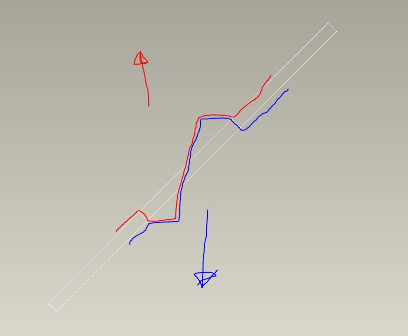
I want to make a hole that is angled 45 degress in a mould opening vertically. I have tried to sketch below how I imagine the mould parts to look like.

draftcross.JPG

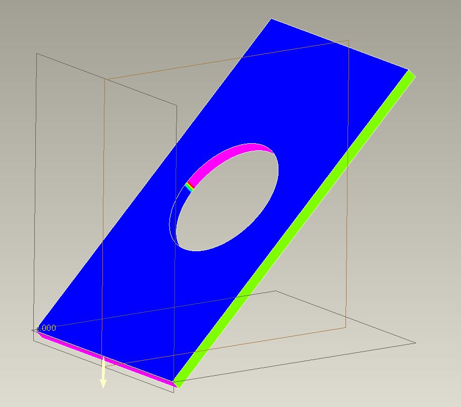
When doing a draft analysis it looks almost fine. I just need to get rid of the "rainbow" area in the middle and have a "clean cut" going from blue to pink with no transisition.

Any good ideas on how to do that?

draft01.JPG

    7 replies

    13-Aquamarine
    June 7, 2013

    Hi Esben...

    I see what you're tyring to do and it should be possible. The obvious issue is where the two "cuts" meet. There's an oddball transition which is what's showing up as the rainbow on the draft analysis.

    You may be able to do this another way- but the first thing I would try is to create a solid volume (using surfaces) that represent the material you're trying to remove. Instead of creating the hole, create surfaces that will be "subtracted" from the solid blue plate thus creating the hole.

    The idea here is that you can't really see why the cut is making that rainbow area.. but by trying to model the core or cavity you're trying to remove, it will become clear. I suspect if you used two surface (not solid) revolves, you'll see where the problem lies. I suspect there's some overlapping geometry that must be dealt with. Again, modeling the core will make it clear.

    Once you understand where the problem is coming from, you can correct it or mitigate it somehow. If you can create the cavity as a surface, you can then use it to cut away the solid plate. Or, you can simply use the knowledge gained from your surface model to help you better understand how to create the hole with more traditional means.

    If you don't get what I'm saying, let me know. Good luck!

    Thanks...

    -Brian

    17-Peridot
    June 7, 2013

    Yep, Brian is right. This is the common issue where people cannot visualize the transition in the die.

    The obvious is that where the rainbow resides, you need a small draft from vertical. It will not be a true circle on one side or the other, or both if the transition is in the middle of the "hole".

    But, this is not the common way of creating this feature. Depending on your flash tolerance, you could come up from one side and stop at the plane or just beyond it into the mating die. It would be a very odd hole that way, however. it could be done with a slide if it was critical enough.

    But to make what you are making, do as Brian suggests. Make a die in the shape of your 1st sketch, square even. Then make it round with a cut the way you want it. Now you will have the edges where your transition will be. Merge>subtract this die from the part (assembly the part/assemble the die/merge-remove the die from the part).

    I'll see a bout making a quick model of this. What version are you on?

    17-Peridot
    June 7, 2013

    Let's see if this helps.

    There is nothing easy about manually making dies for injection molding or die casting. This was a good challenge none the less. The custom made extensions for doing this in Creo work the same way (extensive use of merge features). In this case, I was very deliberate with some of my choices. This is key to understand how you wish to attack each case.

    In this case I used the following assumptions:

    • I want a perfect circle on both sides of the sheet
    • The circle is the same size on both sides (no draft offset)
    • No textures will be present within the hole
    • Minimal zero draft is allowed
    • No slides

    So this is what I came up with:

    hole_at_angle_mold.PNG

    I used a series of sweeps to match ~95% of the circle perfectly (the part that has significant draft naturally).

    I used the merge/cut-out feature to create the hole in the sheet. Personally, I don't like using separate dependent files, but there you go. Now that I have a good visual, I -might- be able to do this ends remove the die's merge features on the work part. Everyone has their own comfort level.

    Now if I did this in the sheetmetal module, I might make the die on the fly using the surfaces. Although I prefer modeling with solid features, to make the female cavity in the die I had to merge surfaces and solidify them.

    Although the questionable region looked small, it actually has negative draft that is rarely allowed although there are cases that this is done on purpose. In general, bad idea. See where the die transition must happened:

    hole_at_angle_neg_draft.PNG

    I assumed a 10 degree die transition angle (mating faces of the die); 2.5 degree standard draft on the part. the orange transition in the next image is well on the way to 2.5 degrees. the green is the 0-draft region necessary to meet my "perfect circle" goal.

    hole_at_angle_mold_close.PNG

    Here you see the analysis on the die (both dies are identical)

    hole_at_angle_die_close.PNG

    The green triangle is the region created as a divergence of 2 sweeps. The majority of the circle sweep is normal to the curve (the scribed circle), but the transition was swept at a normal of the pull direction. This is how the undercut was avoided.

    If you have the full version of Creo 2 (not academic), I can provide the parts to see how I got there. I need to do some cleanup as I got a bit messy for my own tastes. I tried quite a few iterations to get to this result. This one was the most straight forward approach.

    21-Topaz II
    June 13, 2013

    Interesting discussion and creative solution, Antonius.

    I'd like to add a couple things.

    1. The problem isn't simply that you have a 'rainbow' area, it's that that transition from A side to B side isn't aligned with your pull direction. This creates, as Antonius discovered, undercuts on both sides of the circle.
    2. I don't think you need the protruding slide-by shut off, the P/L can be right on the face of the part on each side.
    3. By creating this so that you have a true circle on both sides, you do not have a true thru diameter as material must be added inside the hole to make the part moldable.
    4. With a small bit of surfacing, what Antonius has done can all be done natively in the part which makes the database simpler and keeps all the design dims in the part
    5. If having a circular profile is only important on one side or the other, or even in the center, this can be made quite simply with an extrude and no slide-by shutoffs.

    I've uploaded a zip file showing how to create options 4 & 5 in Creo2.

    17-Peridot
    June 13, 2013

    Doug, you are right that approximations are easier to model and certainly easier to manage.

    Do an analysis on on your simple version. You will still find negative draft in those 2 files. I was working on a similar version to simple_2 where the parting was through the hole at opposite end (skewed oval through the center; image below). It became quite complex from a modeling perspective fairly quickly as I ended up with the dreaded tangent convergence that virtually all CAD systems choke on.

    Also check the boundary blend version. Although it works very much the same, it is still slightly different than the straight forward die version. The remaining interference is slightly less in the version provided. Again, it all depends on the assumption you have to apply to the design intent. I've never been one to "approximate" what I hand a machinist. I much prefer providing true intent.

    approximation.PNG

    Below is that alternate. Although I could make the surface to close the transition gap, due to the tangent interface on the shallow end, I could not get it to solidify. Same old problem. But the idea is sound for a simplified die.

    Alternate.PNG

    Most likely... since the hole is on a high angle, the machinist wouldn't care about the higher post. He/she is machining the face anyway and has plenty of material to make the posts. Why not make the best feature possible. Again... not knowing design intent, it is hard to argue the engineer's choice of requirements.

    17-Peridot
    June 13, 2013

    I did a little more work on the alternative hole.

    New assumptions:

    • Through hole perfectly round at face angle.
    • Minimize deformation at surface
    • No negative draft permitted
    • Zero draft permitted on a limited basis
    • No texture in the hole

    In this case, the draft is offset immediately at separation due to the high draft on the opposite face. Still more zero-draft than the original so total zero-draft analysis of the mold must be considered. No surfaces or approximations.

    No separate die file ...but the work was duplicated for each half. Maybe rotational patterning would save some effort. A lot of prep work for related features. A bit more effort would reduce the feature count. A little more relation work and the hole is easily scalable (think UDF).

    Creo 2.0 and STEP attached

    hole_on_angle_mold_tech.PNG

    hole_on_angle_mold_tech_perfectcircle.PNG

    Physical tooling view (reference - not required in model):

    hole_on_angle_mold_tech_tooling.PNG

    Patriot_1776
    22-Sapphire II
    June 13, 2013

    Nice work Antonius!

    My question to Esben is why make it so complicated? You could WAAAAY more easily (and cheaply) put the shape required for the hole in one side, or, if you wanted to split the draft, put the parting line in the middle of the thickness. What you're doing REALLY complicates everything.

    Is there a reason this absolutely has to be done like this?

    1-Visitor
    June 14, 2013

    Hi all.

    First of all thanks for your help and the attached files. It makes it really easy to understand what you mean.

    I'm amazed by the quality of the answers.


    Then I must say this solution is a bit more complex than imagined.

    To put it into a context. A strain relief has to go through the hole, and I really can't allow much tolerance in order to keep it tight. I tried quickly to split the draft in the middle of the thickness, but I think the gaps are to big.

    pg.JPG

    I think Doug's solution 4 will work quite well, though.


    But again as said previously, I'm maybe doing it way more complex than it has to be. Just can't see how to simplify it when I can't allow too big gaps, other than using some side actions, which also is an option.


    If you have any great ideas, feel free to write'em here

    21-Topaz II
    June 14, 2013

    I'm sure you already looked into if you can change the angle of the mounting surface, that would help a lot if you could get it closer to horizontal.

    You can take that #4 and move the P/L sketch so that the left side is close to the bottom and the right is close to the top to get as much 'true diameter' as possible. It doesn't need to be parallel to the wall.

    Good luck.

    1-Visitor
    June 14, 2013

    Esben,

    How do you intend to fix that insert (strain relief), the wall thickness is not enough?

    Or is the strain relief located in a different mating product?

    Like Doug said, try to see if you can place it horizontal, can't you break the surface or do you need to follow this line?

    Sorry I tried to upload a picture, but I could not submit the post

    Cheers,

    Alain

    Patriot_1776
    22-Sapphire II
    June 14, 2013

    Ok, so, here's my simplified take on this:

    ANGLED_HOLE_DRAFT-01.jpg

    The parting line/shutoff is extremely easy, simple, and cheap: It's flat, halfway thru the part, parallel to the surfaces you'll mate against. On either top or bottom end (in the pic), you get 1/2 the material thickness to locate the strain relief. In the center you get the whole thickness. I added 1deg of draft in the pull direction (normal to the top plane) for sheyts and giggles. From what I saw of your needs, I think this will work just fine. If you absolutely HAD to have the circle as close as possible, then Anonius's solution is what you want. It all depends on your needs.

    I've included the part as well.

    Have fun with it!

    Patriot_1776
    22-Sapphire II
    June 14, 2013

    Here's another take on it. Very similar to what Antonius did in the "silver" model (from the pic, I can't open the models). This gives a very close approximation of the hole, with a slightly more complicated shutoff. It's funny, I first didn't understand why it "lobed" the hole (as it did in his pics too), then I realized what the VSS was doing, and think it did exactly as asked.

    ANGLED_HOLE_DRAFT-02.jpg

    17-Peridot
    June 15, 2013

    Nice Sweep,