
Creo Parametric FreeStyle
- Mark as New
- Bookmark
- Subscribe
- Mute
- Subscribe to RSS Feed
- Permalink
- Notify Moderator
Creo Parametric FreeStyle
Please read the other articles for this month:
- Desktop Tip: Understanding Retrieval Sequence, also by Tom McNaney
- Enterprise Product Focus: What’s New in Windchill 10.0 MPMLink?, and Tip: Reconciliation and eBOM Change Propagation to the mBOM by Mike Maylock
PTC Technical Specialists Newsletter - October 2011
Desktop Product Focus : Creo Parametric FreeStyle
In a recent study by PTC, 81% of respondents agreed with the statement "to be successful in business, you need innovation." Furthermore, respondents indicated that the root of innovation lies in concept design - the earliest representations, sketches, and mock-ups of a new product.
To that end, there are many exciting new capabilities introduced with Creo Parametric that will impact Industrial Design and the Conceptual Design phase through unprecedented flexibility and speed. This design platform is built on a rich legacy of proven power and robustness from the former Pro/ENGINEER, CoCreate, and ProductView solutions while delivering hundreds of new capabilities to boost your design efficiency across the board. In a recent blog post on creo.ptc.com, Paul Sagar introduced Creo Sketch. This FREE purpose-built app can be downloaded and used to replace the familiar napkin sketch when you want to quickly capture your earliest design ideas. As a Creo Parametric user, the natural next step would be to turn that 2D idea into a 3D model. While still working on a conceptual design, you may not yet want to commit to the effort of constructing a fully parametric, feature-based model. Or your shape may be so organic that it would be difficult and tedious to create using traditional modeling approaches. Some example products that would benefit from this approach are automotive interior/exterior components, consumer products, and toys.
Introducing FreeStyle Design Extension
No matter...every license of Creo Parametric now includes the FreeStyle Design Extension! As the name can be interpreted, it is FREE and addresses the need to design with STYLE. Well, as you will see, the Free actually refers to freedom in design! Freestyle offers a set of capabilities to quickly create flexible surface models from scratch, or by tracing over a 2D sketch. The 3D form can be intuitively sculpted by deforming and morphing a control mesh to achieve the desired shape using an intuitive and powerful 3D dragger. The resulting high-quality continuous surfaces can be directly used for the fully-detailed 3D design. This is not a replacement for the powerful surfacing functionality provided by Pro/SURFACE or ISDX which rely on building surfaces from discrete curve boundaries and patch connections. It is complementary, and simply offers more tools so the designer can apply the right tool to the right job. This article will show how to access this module and the essentials for getting started, as opposed to a specific design scenario. (Please see the link at the bottom of this article for a movie showing Freestyle in action)
First, a little background...
Freestyle is based upon subdivisional surface modeling. This modeling technology was first discovered in the late 70's by Edwin Catmull and Jim Clark. Edwin Catmull is known for his work at Lucasfilm, and as a cofounder of Pixar and key developer of RenderMan. Consequently, the Catmull-Clark algorithms are used by most of the 3D modeling packages available today for animation and game development (e.g., Maya, 3D Studio Max). This approach lends itself very well to the rapid creation of free form shapes for rendering. However, most other modelers like these do not create NURBS surfaces suitable for CAD design. Freestyle uses a similar approach with the goal of creating G2 continuous manufacturable surfaces!
The Freestyle modeling environment provides commands to create smooth and well defined B-spline surfaces quickly and easily using a polygonal control mesh with minimal control vertices. You can manipulate and recursively subdivide faces or edges of the control mesh. The positions of the new vertices are calculated based on the positions of the nearby old vertices. This successive process produces a denser control mesh for localized refinements and more control over the underlying shape. The result of a Freestyle feature is a quilt of surfaces corresponding to the control mesh with optional associativity to its references - but no history of the freeform manipulations. These high-quality surfaces can be used just like any other surfaces with editing and construction tools such as trim, merge, thicken, etc.
Accessing Freestyle
Open a new or existing part, and from the Model tab click the Freestyle icon, or use the command search box.

If the following message appears, you may simply need to download an updated license file or reconfigure the startup command to include the Freestyle_Design_Extension (license feature #325).

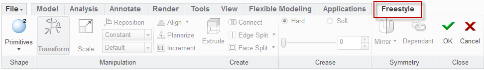
Once the Freestyle Modeling environment is activated, an additional tab will appear on the Ribbon UI:
Trace Sketch
As an optional but very common starting point, use Trace Sketch to import, scale, and reposition 2D raster images onto one or more planes. These act as a backdrop or underlay for the conceptual designer to trace over and sculpt the 3D model.
Trace Sketch can be accessed from the View tab before or during the creation of the Freestyle feature. Once activated, an additional tab will appear on the Ribbon UI. Click Add to load and place 2D raster images.

Note the other options, like setting a transparency color or global transparency value. Fit will size the image to a precise dimension using two calibration points.
Freestyle Primitives
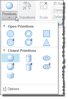
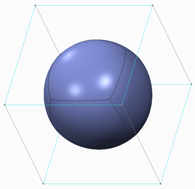
A Freestyle feature starts with a primitive shape which may be chosen from a fly-out gallery.
Each primitive shown in the palette comes with a default control mesh and will be placed relative to the default Coordinate System.
Only one primitive element can be included in each Freestyle feature. If a new primitive is selected, it will replace the previous one. An unlimited number of Freestyle features may be created in a model.
Standard selection techniques apply. The selection filter can be used to target control mesh elements (vertex, edge, face). Use the RMB for query select. Use the CTRL key to toggle selection and the inclusion of multiple elements in the selection set. Select on the graphics area outside the model/mesh to clear the selection buffer. See table below for advanced techniques.
A 3D handle will appear for dynamic manipulation.
Manipulation - Transform & Scale
The 3D handle is used to intuitively drag the selected mesh elements using operations such as translate, rotate, and scale. (Note, this is the same graphical tool used in other areas like Flexible Modeling and Assembly Component positioning.) The manipulation mode can be set from the ribbon or with the new Circular menu. This new interface tool will appear when right-clicking outside the 3D handle. It follows the philosophy of focusing on the modeling task while minimizing mouse travel.
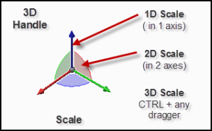
Elements of the 3D handle will prehighlight while moving the mouse over them. Select and drag to constrain movement as shown in the figures below and according to the manipulation mode. The Increment command toggles the display of the drag dimension. Select Primitives > Options to set the increment values.
- axis arrows for 1D translation / scale
- semi-circles for 1D rotation
- wedge between axes for 2D planar translation / scale
- central sphere for free 3D translation. For 3D scaling, hold CTRL and drag any axis.

Right-click within the 3D handle to display a pop-up context menu of shortcuts for use with the handle. Reposition will stay active until un-checked. Use the draggers to reposition the 3D handle. Use the central sphere and SHIFT to snap to mesh elements or datum references.
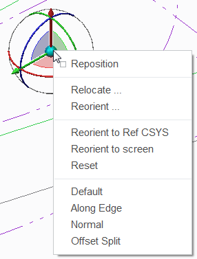
Right click [and hold] outside the 3D handle to display the Circular menu. The commands on this menu are convenient shortcuts to those present in the Ribbon, but do not offer all the same options. Hover to display a tool tip. The small blue arrow is an indication that there is a fly-out to access related commands.
Advanced Selection
For refinement, it may be necessary to select multiple elements. Here are all the available selection mechanisms:
| Selection Type | Selection Reference |
|---|---|
| Filter | Select one or more mesh elements (vertex, edge, face) using the selection filter on the status bar. You can also use the filter to select planes and planar surfaces when you perform the mirror and align operations. |
| Complete Loop | Select an edge or a face, hold down the SHIFT key and select other mesh elements to include in the loop. Select the same edge or face that you selected initially to complete the loop. |
| Partial Loop | Select one or more mesh elements of different types, for example, faces, vertices, and edges. Hold down the SHIFT key and select mesh elements of the same type as the previous selection to create a partial loop. |
| Multiple Loops | Use the complete loop or partial loop selection methods to select the first loop. Hold down the CTRL key and select a new mesh element. Then hold down CTRL+SHIFT keys to select the next loop. |
| Region | Drag the pointer to create a rectangular box and select all the mesh elements within the box. The elements are selected based on the selection filter. Hold down the CTRL key and drag the pointer to create a new box to add to the selection set. |
Refine
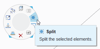
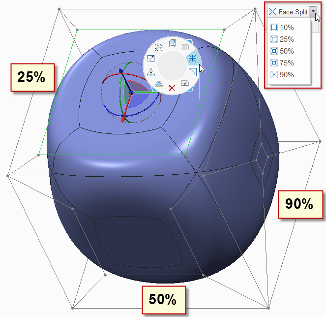
It is often necessary to have more control in an area. Split is used to subdivide the selected element(s). The command on the Circular menu applies a 25% split; use the drop-down commands in the ribbon for other percentages. Middle-click to repeat the split. This MMB shortcut can also be used to repeat other commands.
If you Delete control faces, this will remove the underlying surface. Faces that would result in disconnected geometry cannot be deleted. The holes can be filled using Connect to restore or create new control faces. Connect can also be used to join between "opposing" faces.
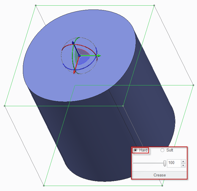
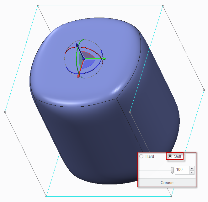
The shape of a Freestyle surface can be further refined by applying a hard or soft crease to the selected elements. Creasing adjusts the weight applied to the edges and vertices so that the associated surfaces fit properly within the volumetric control mesh. Set the crease type and value via slider or entry box. The Circular menu shortcut will toggle the value between 0 and 100.
Hard Crease - Sharpens the edges and generates a hard edge between the surfaces. For example, if you have selected a sphere as the primitive, convert it to a cylinder by applying 100% hard crease to its top and bottom faces.
Soft Crease - Creates smooth and tighter transitions between surfaces. For example, a 100% soft crease applied to a sphere gives it the effect of an edge round.
The images below show No Crease, 100% Hard Crease, and 100% Soft Crease. (click on image to zoom)

Construction Elements
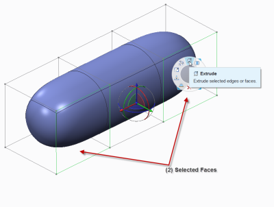
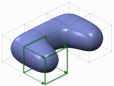
Extrude enables you to add new faces and border edges on the control mesh. The new faces are created by duplicating the selection, then connecting it to the original face with parallel edges. The extrude length is equal to the shortest edge of the selected mesh elements. You can extrude either faces or edges, and multiple items at once. If both edges and faces are selected, the first selection type is retained. That is, if you first selected faces and then edges, all the edges would be discarded. Any vertices in the selection are automatically ignored. This is a powerful command to extend the form by morphing.
Mirror enables you to create symmetrical Freestyle geometry by projecting the selected control mesh onto a mirror plane (datum plane or planar surface). The mirrored geometry is displayed, but not its mirrored control mesh By default, changes to the control mesh are automatically reflected in the mirrored geometry. This dependency can be toggled with the Dependant command. In such cases, portions of the mesh that are still unchanged can be made dependent again on the original mesh. Portions of the mesh that have changed since they were made independent cannot be made dependent again. Only one mirror can be created within a single Freestyle feature.
Keep in mind that Undo and Redo are available within the Freestyle modeling environment. Use the familiar Ctrl+Z and Ctrl+Y respectiviely to affect the most recent change in the stack. It may be helpful to add these to the Quick Access Toolbar. Enjoy the freedom to be creative and explore design possibilities!
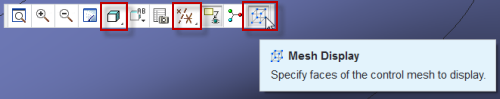
Display Options
There are several options to control the appearance and aid in the visual design. The Graphics Toolbar, embedded by default at the top of the graphics window, can be used to set the shading type, and toggle the display of datum features and the control mesh. Turning off the control mesh and enabling Shading With Edges can be helpful when refining the shape.
It is also recommended that the following options be set under File > Options:
- Model Display > Set shade quality to: 10 (shade_quality 10)
- Entity Display > Edge quality display: Very High (edge_display_quality very_high)
Surface Analysis
With few exceptions, the resulting surfaces are extremely high quality, G2 continuous. The first image is displayed with shading with edges as well as the [faint] control mesh. With the edges displayed, you can see that each control face actually has an underlying surface patch. The second image depicts zebra striping from Analysis > Inspect Geometry > Reflection to reveal the continuity and smooth connections.

Complete Freestyle, Add Features
The Freestyle "super-feature" will appear ordered in the Model Tree along with other "standard" Creo features. It is possible to add multiple Freestyle features to the design. Using standard Creo Parametric operations and features, the quilt can be trimmed or merged with other quilts, then thickened to form a solid. Additional features like extrusions, ribs, and rounds can be added to complete the detailed design. If the Freestyle feature is redefined, the intelligence and associativity in Creo Parametric will ensure that the changes are reflected upon regeneration.
Conclusion
- Creo 1.0 is not a typical 1.0 release because there are no functional gaps between Pro/ENGINEER Wildfire 5.0 and Creo 1.0. It is based on the proven stability and robustness of former Pro/ENGINEER releases.
- You can move your data forward confidently with no loss of fidelity or design ability.
- Short learning curve to use the Freestyle modeling environment
- High-quality surfaces can be developed very quickly
- Integral and seamless with Creo Parametric - resulting surfaces are fully interoperable
- Introduces new capabilities to drive innovation and improve Conceptual and Industrial Design
As a customer on active maintenance, you can download the latest release and latest license pack required to enable the Freestyle feature. Why not give it a try? Good Designing!
References and More Information:
- Creo Parametric Help Center - FreeStyle Overview
- PTCstudio channel on YouTube - FreeStyle Demonstration
- Ray Kurland's Blog - Interview with Paul Sagar
- Concept Design Methods for Developing Winning Products by Mike Campbell
This thread is inactive and closed by the PTC Community Management Team. If you would like to provide a reply and re-open this thread, please notify the moderator and reference the thread. You may also use "Start a topic" button to ask a new question. Please be sure to include what version of the PTC product you are using so another community member knowledgeable about your version may be able to assist.
- Labels:
-
Surfacing
- Mark as New
- Bookmark
- Subscribe
- Mute
- Subscribe to RSS Feed
- Permalink
- Notify Moderator
Good stuff on Freestyle modeling
Hardhyan


