
Turn on suggestions
Auto-suggest helps you quickly narrow down your search results by suggesting possible matches as you type.
Showing results for
Please log in to access translation
Turn on suggestions
Auto-suggest helps you quickly narrow down your search results by suggesting possible matches as you type.
Showing results for
Community Tip - When posting, your subject should be specific and summarize your question. Here are some additional tips on asking a great question. X
- Community
- Creo+ and Creo Parametric
- Manufacturing (CAM)
- Did You Know? PTC Creo 3.0 Enhancements: Bend Tool
Translate the entire conversation x
Please log in to access translation
Options
- Subscribe to RSS Feed
- Mark Topic as New
- Mark Topic as Read
- Float this Topic for Current User
- Bookmark
- Subscribe
- Mute
- Printer Friendly Page
Did You Know? PTC Creo 3.0 Enhancements: Bend Tool
Jul 01, 2015
02:53 PM
- Mark as New
- Bookmark
- Subscribe
- Mute
- Subscribe to RSS Feed
- Permalink
- Notify Moderator
Please log in to access translation
Jul 01, 2015
02:53 PM
Did You Know? PTC Creo 3.0 Enhancements: Bend Tool
The graphical performance and capabilities of PTC Creo have been enhanced in version 3.0. This post will cover how bend relief creation is enhanced in the PTC Creo Parametric Sheet Metal Design Bend Tool. Don Breda, CAD Product Manager, explains how bend reliefs are automatically created for you in PTC Creo 3.0:
In PTC Creo 3.0 bend reliefs are now automatically placed at the ends of bend lines and as needed along each line. This bend line relief handling means that you can quickly and easily bend a portion of an existing wall into a tab. To create a bend, select the Bend function in the Bends group on the Model tab in a Sheet Metal part. This will open the Bend Tool dashboard. Select an edge as a reference, and use the offset dragger to locate the bend line offset from that edge.
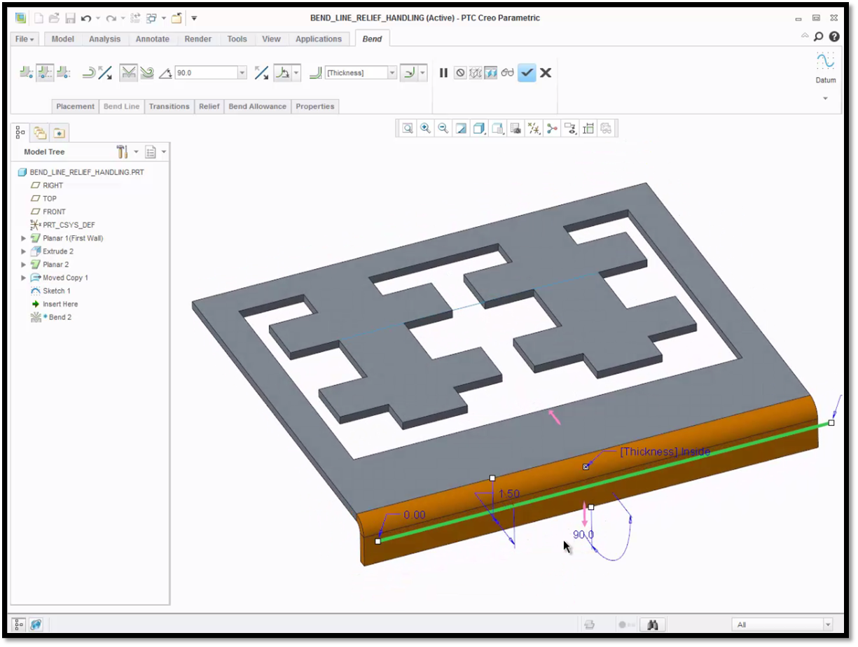
The bend line on this part is offset 1.50 inches from the reference edge.
Trim your bend line by dragging the handles at the ends, or manually enter a value for the end offset. The system will automatically place the default reliefs at the ends of the bend line. The default relief type is Rip for the sheet metal part templates that ship with the system. To change the relief, select the Relief panel in the Bend Tool dashboard, and choose your preference from the drop-down menu. You can define your reliefs as No Relief, Rip, Stretch, Rectangular, or Obround. If you change the relief type to No Relief, the bend is extended to the end of the part.
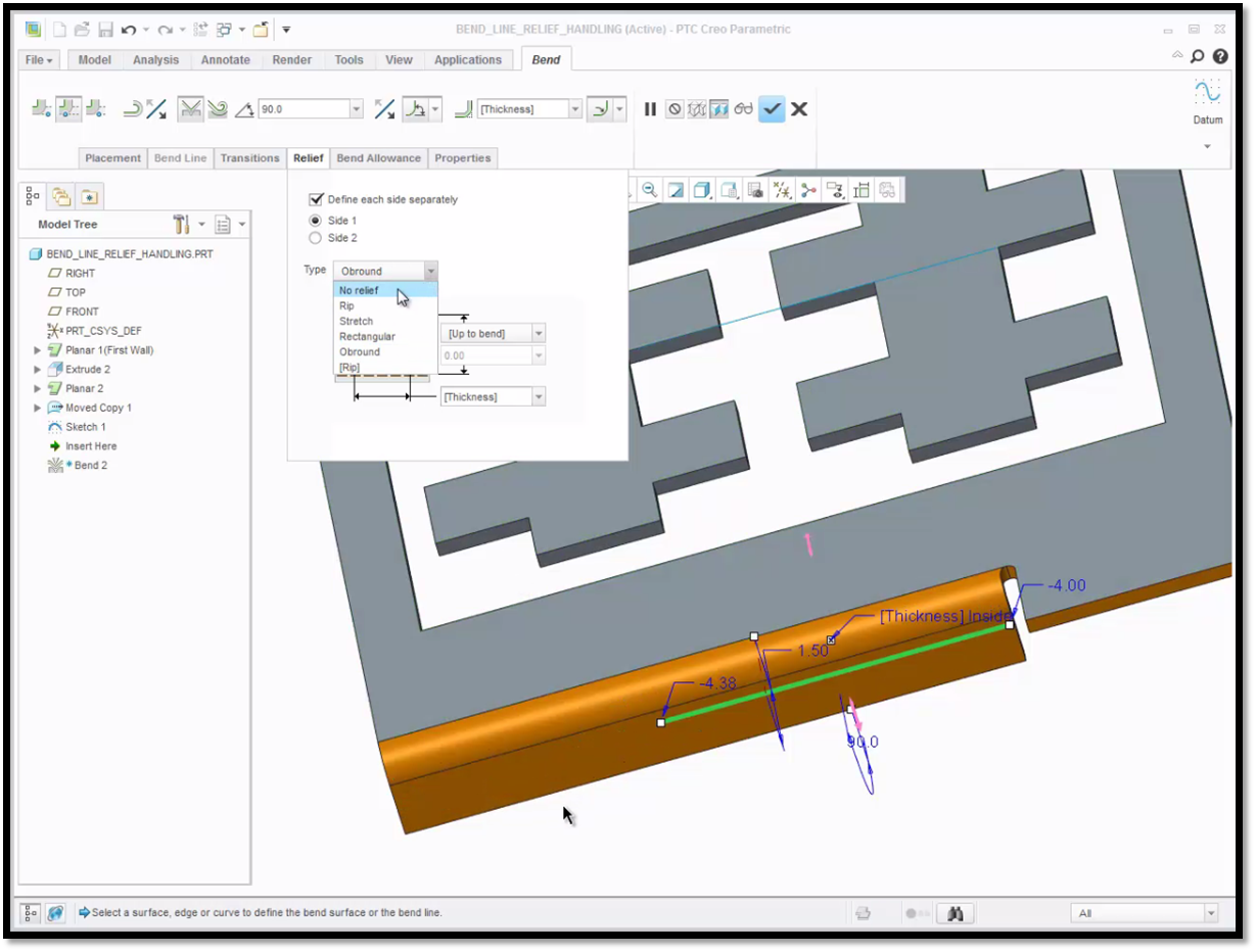
On this part, the reliefs were changed to Obround for one side and No Relief for the other side.
The Bend Tool has also been enhanced to create bend reliefs as needed along the bend line. It will create multiple bend reliefs along a single bend line, where they are appropriate. If you place your single bend line across multiple tabs, the system will automatically bend each tab along your bend line and place the bend reliefs that are defined. Previously, this would have required the use of two features.
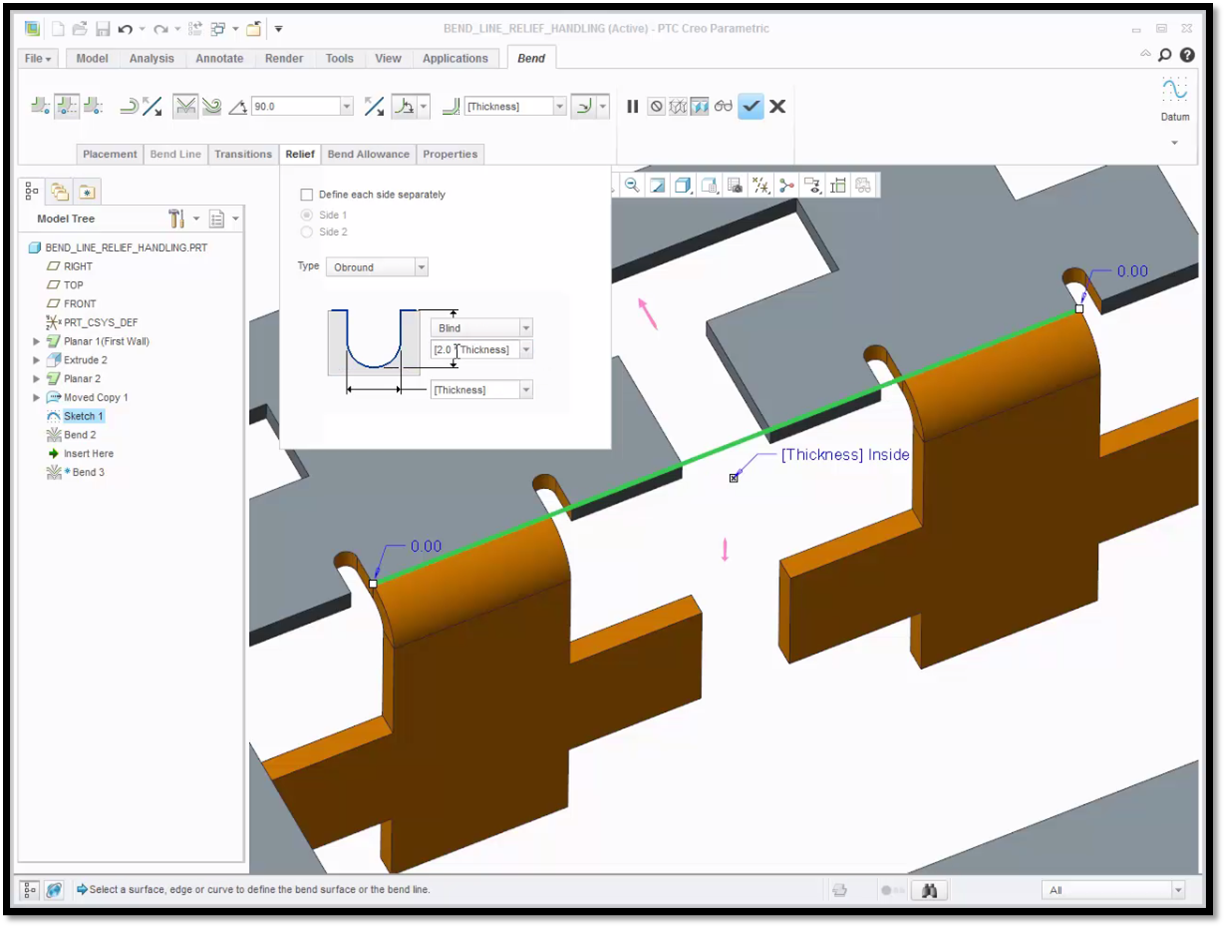
Two tabs are bent and given reliefs on each side that extend beyond the bend line.
To learn more about the sheet metal bend tool, check out our video tutorial on the PTC Creo University Learning Exchange (“Using Bend Reliefs”).
Stay tuned to our “Did You Know” blog series as we cover all of the exciting, new enhancements in PTC Creo 3.0.
For more in-depth product feature explanations, visit our Tech Tips area.
Have some ideas about what PTC Creo product features you’d like to learn more about? Send me a message or leave a comment below and we’ll write up the best ideas from the community. Thanks for reading, looking forward to all of your feedback!
In case you missed it, check out our recent Did You Know posts covering PTC Creo 3.0 enhancements:
1) Did You Know? PTC Creo 3.0 Enhancements: Additive Manufacturing (3D Printing)
2) Fast Facts! Quick Tips for Using PTC Creo - Part Modeling Part 2
3) Did You Know? PTC Creo 3.0 Enhancements: 3D Thickness in PTC Creo Parametric
This thread is inactive and closed by the PTC Community Management Team. If you would like to provide a reply and re-open this thread, please notify the moderator and reference the thread. You may also use "Start a topic" button to ask a new question. Please be sure to include what version of the PTC product you are using so another community member knowledgeable about your version may be able to assist.
0 REPLIES 0
Announcements


Top Tags
