
Turn on suggestions
Auto-suggest helps you quickly narrow down your search results by suggesting possible matches as you type.
Showing results for
Please log in to access translation
Turn on suggestions
Auto-suggest helps you quickly narrow down your search results by suggesting possible matches as you type.
Showing results for
Community Tip - Visit the PTCooler (the community lounge) to get to know your fellow community members and check out some of Dale's Friday Humor posts! X
- Community
- Creo+ and Creo Parametric
- Manufacturing (CAM)
- Re: Trajectory Milling
Translate the entire conversation x
Please log in to access translation
Options
- Subscribe to RSS Feed
- Mark Topic as New
- Mark Topic as Read
- Float this Topic for Current User
- Bookmark
- Subscribe
- Mute
- Printer Friendly Page
Trajectory Milling
Oct 13, 2016
11:24 AM
- Mark as New
- Bookmark
- Subscribe
- Mute
- Subscribe to RSS Feed
- Permalink
- Notify Moderator
Please log in to access translation
Oct 13, 2016
11:24 AM
Trajectory Milling
Had some free time to work on this today. Source link
I created a curve by equation and used that to drive a trajectory milling sequence for some long slots I needed to mill.
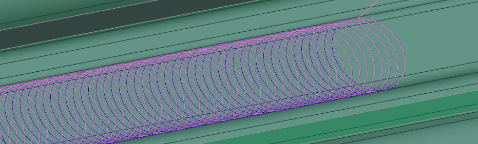
here is the equation I used to create this curve.
/* ENTER TOOL STEP OVER
SO = 0.05
/* EMPIRICAL VALUE TO CORRECT SHAPE ERROR
SF = 0.0175
/* ENTER PROFILE ALLOWANCE (STOCK)
PA = 0.005
/* ENTER TOOL CUTTER DIAMETER
CD = .3937
/* ENTER SLOT WIDTH
SW = 0.811977
/* ENTER NUMBER OF REVOLUTIONS
N = 100
A = ( ( SO * SF ) / 3.141592654 ) / 2
B = ( ( SW - ( 2 * PA ) ) - CD ) / 2
x = ( A * ( t * N * 360 )) - ( B * sin ( t * N * 360 ) )
y = ( B * cos ( t * N * 360 ))
z = 0
I don't understand what the shape error value is about but it seems to work for this application. Just thought i should share this with everyone in case they wanted to use it or improve it 
This thread is inactive and closed by the PTC Community Management Team. If you would like to provide a reply and re-open this thread, please notify the moderator and reference the thread. You may also use "Start a topic" button to ask a new question. Please be sure to include what version of the PTC product you are using so another community member knowledgeable about your version may be able to assist.
Labels:
- Labels:
-
General
15 REPLIES 15
Oct 13, 2016
11:44 AM
- Mark as New
- Bookmark
- Subscribe
- Mute
- Subscribe to RSS Feed
- Permalink
- Notify Moderator
Please log in to access translation
Oct 13, 2016
11:44 AM
Nick,
Nice looking tool path !
Oct 13, 2016
11:47 AM
- Mark as New
- Bookmark
- Subscribe
- Mute
- Subscribe to RSS Feed
- Permalink
- Notify Moderator
Please log in to access translation
Oct 13, 2016
11:47 AM
Thank you
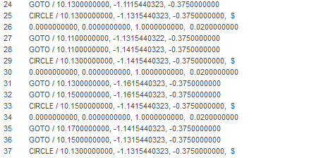
I'm finding that the cl data and g-code is all points so now am looking into arc fitting but not sure if this is a wise move.
Oct 13, 2016
04:34 PM
- Mark as New
- Bookmark
- Subscribe
- Mute
- Subscribe to RSS Feed
- Permalink
- Notify Moderator
Please log in to access translation
Oct 13, 2016
04:34 PM
Interesting application.
If you are using creo3you can do something similar using volume-mill and the cl data isn't all pts. This would allow you to control tool selection and parameter adjustment normally. You can also do slots that aren't straight.
Josh

Oct 13, 2016
04:56 PM
- Mark as New
- Bookmark
- Subscribe
- Mute
- Subscribe to RSS Feed
- Permalink
- Notify Moderator
Please log in to access translation
Oct 13, 2016
04:56 PM
oooh i like the look of that cl data but volumill is extra $ correct?
Oct 13, 2016
05:00 PM
- Mark as New
- Bookmark
- Subscribe
- Mute
- Subscribe to RSS Feed
- Permalink
- Notify Moderator
Please log in to access translation
Oct 13, 2016
05:00 PM
Don't know, sorry.
Josh
Oct 14, 2016
12:51 PM
- Mark as New
- Bookmark
- Subscribe
- Mute
- Subscribe to RSS Feed
- Permalink
- Notify Moderator
Please log in to access translation
Oct 14, 2016
12:51 PM
Joshua - was that curve created using a "Volume Milling" sequence in Creo (constant load?), or using the third-party "VoluMill" addon from Celerative?
Oct 14, 2016
04:07 PM
- Mark as New
- Bookmark
- Subscribe
- Mute
- Subscribe to RSS Feed
- Permalink
- Notify Moderator
Please log in to access translation
Oct 14, 2016
04:07 PM
Creo "Volume Milling" with constant load, need creo3 and there are required parameter settings to keep the tool down.
Josh
Oct 14, 2016
04:35 PM
- Mark as New
- Bookmark
- Subscribe
- Mute
- Subscribe to RSS Feed
- Permalink
- Notify Moderator
Please log in to access translation
Oct 14, 2016
04:35 PM
Joshua - Thanks for the response. The toolpath looks promising. I believe I read an earlier thread that detailed the parameters required.
We're still Creo2, but moving up to the next release of Windchill this weekend, so we're getting closer to new releases of Creo.
Oct 14, 2016
12:48 PM
- Mark as New
- Bookmark
- Subscribe
- Mute
- Subscribe to RSS Feed
- Permalink
- Notify Moderator
Please log in to access translation
Oct 14, 2016
12:48 PM
I haven't been doing any programming for a couple years now, but was reading through the forum to see what's new. I used a similar technique as Nick and also didn't have an accurate solution to the step-over value - I just tweaked the STEP value to get what I needed. I didn't use it frequently enough to invest time resolving the step over issue.
Throchoidal milling curve: I used a CSYS to anchor the start of the curve orientation of the path - the default vector for the path is Y+. I could also juggle the X/Y calculations to control the vector and climb/conventional cutting condition as shown in the example.
/*-------------------------------------------------------------------
/*
/* RAD = radius of path (slot_radius - cutter_radius)
/* STEP = determines "step-over", **STILL GUESSING ON VALUE**
/* DIST = total travel distance
/* DEGS = CALCULATED, DEGREES: distance_required/step*2*360
/* ------- FORMAT -------
/* x = (STEP-RAD*cos(t*DEGS))-STEP
/* y = STEP*((t*DEGS*STEP*3.14159)/360) - RAD*sin(t*DEGS)
/* z = 0.
/*
/* -- OPTIONAL -- ADD THE FOLLOWING PARAMETERS TO THE ASSEMBLY --
/* NR: RAD (REAL NUMBER, 0.0)
/* NR: STEP (REAL NUMBER, 0.0)
/* NR: DIST (REAL NUMBER, 0.0)
/* NR: DEGS (REAL NUMBER, 0.0)
/*
/*
/*------------------------------------------------------------------
/* -- IN SAMPLE BELOW X/Y REVERSED FOR X+ ADVANCING CUTS
/* -- IN SAMPLE BELOW Y IS REVERSED FOR CLIMB: "-(STEP" & "+STEP"
RAD=.03
STEP=.095
DIST=2.
DEGS=(DIST/STEP)*720
Y = -(STEP-RAD*COS(t*DEGS))+STEP
X = STEP*((t*DEGS*STEP*3.14159)/360) - RAD*sin(t*DEGS)
z = 0.
Oct 21, 2016
09:58 AM
- Mark as New
- Bookmark
- Subscribe
- Mute
- Subscribe to RSS Feed
- Permalink
- Notify Moderator
Please log in to access translation
Oct 21, 2016
09:58 AM
Set hidden option in your config.pro
trochoid_milling yes
Then in your parameters of 3 axisTrajectory miling appears 2 additional parameters:
TROCHOID_WIDTH and TROCHOID_STEP
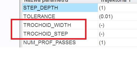
and then you can use it.
Oct 22, 2016
09:23 AM
- Mark as New
- Bookmark
- Subscribe
- Mute
- Subscribe to RSS Feed
- Permalink
- Notify Moderator
Please log in to access translation
Oct 22, 2016
09:23 AM
Oct 24, 2016
06:33 AM
- Mark as New
- Bookmark
- Subscribe
- Mute
- Subscribe to RSS Feed
- Permalink
- Notify Moderator
Please log in to access translation
Oct 24, 2016
06:33 AM
Hello Tomasz,
I have the question.
How the Trajectory sequence should be defined to be able to create such trochoidal milling ?
Thank you.
Rostislav
Oct 28, 2016
08:20 AM
- Mark as New
- Bookmark
- Subscribe
- Mute
- Subscribe to RSS Feed
- Permalink
- Notify Moderator
Please log in to access translation
Oct 28, 2016
08:20 AM
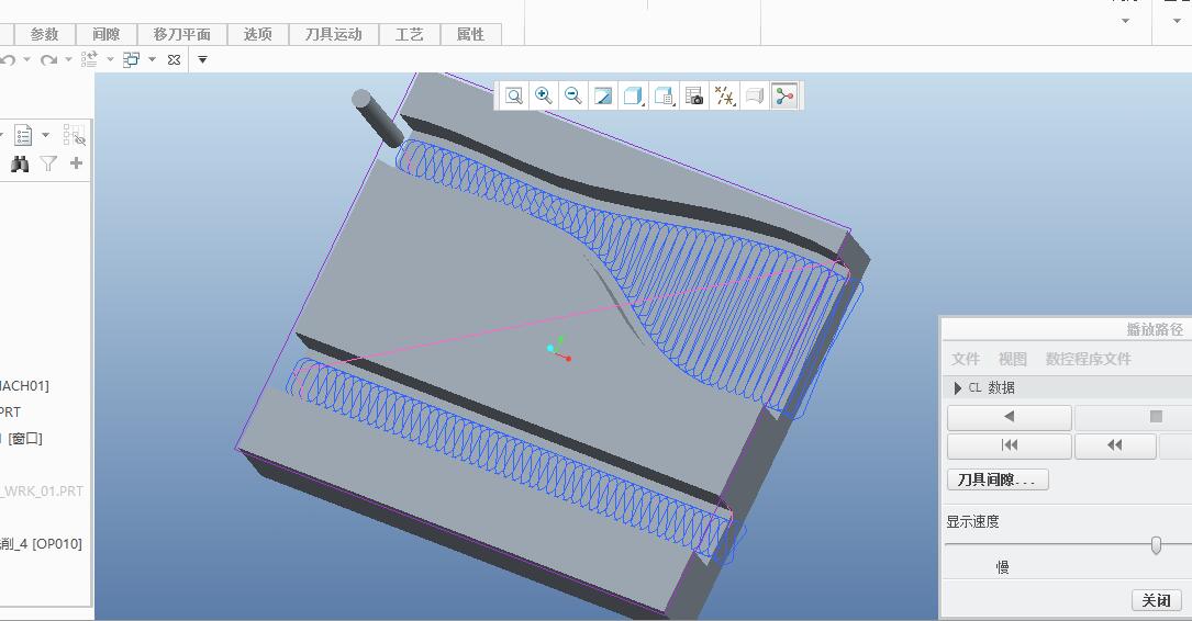
You can use Trajectory milling with hidden parameters. First you must add TROCHOID_MILLING parameter to your config.pro and set it to YES. Then in Trajectory milling apears 2 additional parameters TROCHOID_WIDTH and TROCHOID_STEP. If you set its, your path will be trochoidal. In this case you should be carrefur because tool gauges a milling part. You must measuring slot and use right parameters. This functionality will be officially in creo 4.0 and maybe it will be works better.
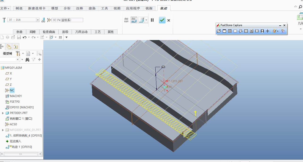
Above chuyxq chu used propably Volume milling or Raughing with Constant Load value in Scan Type parameter. Additional uesed MIN_RETRACT_DIST. Value of this parameter should be large for example max length of milling part. Then tool should stay on milling surface. If you set any small value of LIFT_TOOL_CLEARANCE, you tool lifts above part.
Oct 24, 2016
03:42 PM
- Mark as New
- Bookmark
- Subscribe
- Mute
- Subscribe to RSS Feed
- Permalink
- Notify Moderator
Please log in to access translation
Oct 24, 2016
03:42 PM
Hello Tomasz,
From which build code can you set this hidden config.pro setting? At the moment i am working with Creo 3.0 M070. I don't want to update to the latest with all the failures that's going on with Module works at moment.
Kind regards,
Paul
Oct 28, 2016
08:27 AM
- Mark as New
- Bookmark
- Subscribe
- Mute
- Subscribe to RSS Feed
- Permalink
- Notify Moderator
Please log in to access translation
Oct 28, 2016
08:27 AM
Hello
It should works since Creo Elements/Pro 5.0.

Announcements


Top Tags
