1-Visitor
November 17, 2015
Solved

Plot shear force and moments in Mathcad

  • November 17, 2015
  • 8 replies
  • 24482 views

Hello all,

We are learning shear force and moments and we are drawing them by hand. I understand all the calculations and how to draw shear force and bending moment diagrams but the bonus question on our assignment is to plot the diagram below in Mathcad using x-y graphs. If someone could help me with it I would really appreciate it. We Wont be taught how to do it in Mathcad but i am sure it would be useful to know.

Best answer by MJG

Now that you have solved the problem, attached is my take on it.  Certainly not the only way.

A few things to note:

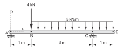
1.) Instead of defining functions with numerical values (either given or calculated), I assign a variable to each piece of information and then use the variable in the function definitions.  This is crucial in “real-world” use of Mathcad for adjustability & reusability.  Image you’re working on a project where the initial design is as shown in your problem, but then the 1m cantilever is later changed to 1.5m.  In your document, you’ll need to go through and make the adjustment in each equation.  In my document, you just change one variable.

2.) I used “option 2” to define M(x).  See if it makes sense to you.  As an added bonus, I showed (on sheets 4-5) how to back-calculate the moment equations for each segment.

3.) Add descriptive text.  I was lazy and did not do this in the attached document.  However, text is very important to give the reader an explanation of what the equations show.

8 replies

1-Visitor
November 17, 2015

I would suggest that you provide your workings to save collabs having to search for the correct formulae.

Mike

23-Emerald I
November 17, 2015

Not your problem, but an example of how you can do it

1-Visitor
November 17, 2015

1st step: solve for your reactions at A & C in Mathcad and post your file (if working in one of the Prime versions of Mathcad, it's also good to post a screenshot).  I'll give you the 2nd step once you complete the 1st.

23-Emerald V
November 17, 2015

Matt Hastie wrote:

Hello all,

We are learning shear force and moments and we are drawing them by hand. I understand all the calculations and how to draw shear force and bending moment diagrams but the bonus question on our assignment is to plot the diagram below in Mathcad using x-y graphs. If someone could help me with it I would really appreciate it. We Wont be taught how to do it in Mathcad but i am sure it would be useful to know.

If you have to draw that particular diagram using Mathcad x-y graphs, that's more than just a bonus question.   It involves, creating expressions/functions to describe the bar, the arrow heads, the numbers, the letters and the support shadings.  It can be done, but it's not simple.  See this link for very good library of routines to draw such things: Creating Amazing Images with Mathcad 14

And have a look at Hatch or Shading of a Region of a Plane

Stuart

1-Visitor
November 17, 2015

I believe he meant that he has to plot the shear & moment diagrams (example) for that particular case.

23-Emerald V
November 17, 2015

Mark Gase wrote:

I believe he meant that he has to plot the shear & moment diagrams (example) for that particular case.

OK.  That's simple enough.  I misread the question, and thought that his saying he knew how to draw shear and moment diagrams meant he knew how to draw those in Mathcad, but didn't know how to draw a diagram that showed the force loadings at each point (again, if it's just a "stick man" diagram, not too difficult but an annotated diagram needs a little bit more work)

Stuart

mhastie1-VisitorAuthor
1-Visitor
November 17, 2015

I have solved for the reactions at A and C. This is as far as we have gone.

1-Visitor
November 17, 2015

Matt, good work so far.

The next step is to create a function that defines the shear force given "x", i.e. define V(x).  You may find it easiest to create three separate functions: one for shear between A & B, one between B & C, and one between C & D.  Remember, however, that the origin of x is always at A for all three equations.  Then there are a few ways to combine them into one function.

mhastie1-VisitorAuthor
1-Visitor
November 18, 2015

OK. This is what I came up with. It makes sense to me but I honestly don't know how it has to be input into Mathcad for it to function properly. I'm taking Construction Engineering at Niagara Collage. I'm using a licensed Mathcad 15.

1-Visitor
November 18, 2015

Matt - you're so close!  You'll need to use the AND operator (upside-down "V") instead of the OR operator (right-side-up "V"):

V(x) = | ...

          | VBC(x) if x>1 AND x<4

          | ...

Alternatively, Mathcad will allow you to write it as:

V(x) = | ...

          | VBC(x) if 1<x<4

          | ...

Next try to graph it.  Note that Mathcad graphs don't handle units, so you need to divide each axis input by the unit you want graphed.

mhastie1-VisitorAuthor
1-Visitor
November 18, 2015

I sort of have it working. I'm obviously missing something. How do I get the numbers to show correctly on the left side? How do I get -11 to connect with 5 and is it possible to

have a line through zero?

1-Visitor
November 18, 2015

You beat me on the reply.  I see you already corrected V(x) and have a plot.

Mathcad is plotting in its default units: Newtons & meters.  You're lucky that you want meters, so the x-axis looks good.  However, I would recommend dividing each axis input by its intended unit.  This helps to annotate your graph, too.

Play with some of the plot features: right-click, Format.  You can display gridlines if you want.  I don't know if you can only display zero, though.  If you need it, we can add a plot of zero.

mhastie1-VisitorAuthor
1-Visitor
November 18, 2015

Mark Gase wrote:

You're lucky that you want meters, so the x-axis looks good.  However, I would recommend dividing each axis input by its intended unit.  This helps to annotate your graph, too.

I don't know what you mean when you said "I would recommend dividing each axis input by its intended unit."

mhastie1-VisitorAuthor
1-Visitor
November 18, 2015

Did I nail it? When I click on the table I can see max 9.6 and min -2.5, is there a way to make them stay on the table when it is deselected?

1-Visitor
November 18, 2015

Congratulations - looks good!

You cannot get the the max & min values to show on the graph like that (at least as far as I know), but here is a way to calculate the maximum value:

Similar calculations can be used to determine the minimum.