Community Tip - You can change your system assigned username to something more personal in your community settings. X
- Community
- PTC Education
- PTC Education Forum
- Challenges with assembly in Creo Parametric
- Subscribe to RSS Feed
- Mark Topic as New
- Mark Topic as Read
- Float this Topic for Current User
- Bookmark
- Subscribe
- Mute
- Printer Friendly Page
Challenges with assembly in Creo Parametric
- Mark as New
- Bookmark
- Subscribe
- Mute
- Subscribe to RSS Feed
- Permalink
- Notify Moderator
Challenges with assembly in Creo Parametric
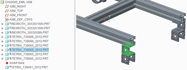
How does one control what parts and assemblies are visible when in edit definition with Creo Parametric 2.0? Oftentimes when having to re-lay out a Tetrix or 80/20 or Rexroth channel assembly when one highlights the one member the adjacent ones that I am trying to constrain to disappear. This disappearnace occurs from both the tree and from the workspace. If one selects "activate" all the other parts show up grayed out but "edit definition" is not available when a part is made active rather than the top tree structure. This behavior does not express itself with Creo Direct 2.0 which I have started to use for laying out the components but unfortunately does not give me the necessary granularity and control over constraints.
A basic robot model can be found in...
https://www.dropbox.com/sh/in2c8ab6o5yqr48/EMxzN8sAxu
This effect also happens with 4 simple Tetrix Channels assembled in a rectangular fashion to form a chassis.
Best Regards,
Emil
Solved! Go to Solution.
Accepted Solutions
- Mark as New
- Bookmark
- Subscribe
- Mute
- Subscribe to RSS Feed
- Permalink
- Notify Moderator
Items are visible if they are defined earlier in the model sequence and will not be visible if they are defined later in the sequence than the component or feature you are redefining.
You can change the order of the component or feature to a later location or move the items you want to use as references to be earlier than the one you are redefining by picking them in the model tree and dragging them to a new spot. This will also force items that must be earlier (moving up the tree) or must be later (moving down the tree) to be moved along with the item.
The differerence between the two products is that Creo Parametric is a procedural modeler and Creo Direct is not, which means with Creo Parametric you are creating a program that starts with the first feature and procedes down the model tree to create the geometry. It's like any procedure in that a particlar step can't refer to the results of steps that haven't happened yet. Creo Parametric automatically removes those items you can't refer to when you redefine an item.
- Mark as New
- Bookmark
- Subscribe
- Mute
- Subscribe to RSS Feed
- Permalink
- Notify Moderator
Wow! Thanks a bunch, incredibly quick response. Now I wish I would have posted my challenge to this board much earlier :-). In reality this is perfect timing, without the previous struggles this eureka moment wouldn't feel as liberating and ecstatic as it feels now. Perfect timing, I'd say. I thought it was, video card issues, etc, etc, etc. Hours of watching tutorials, clicking here, clicking there, re-constraining parts and assemblies... Thanks for being such a proactive, responsive and helpful board.
Best regards to the forum members, and espeially David Schenken and Scott E Morris from PTC for confirming and following up to the correct answer,
Emil
- Mark as New
- Bookmark
- Subscribe
- Mute
- Subscribe to RSS Feed
- Permalink
- Notify Moderator
David is right on with his explanation. If you use the Edit Definition action on the selected component, the two following it will be removed from the model tree and the display since they were added AFTER the currently selected component. You can move components up and down in the heirarchy of the tree, but you cannot move a component before any of its "parents". By parent, I am referring to any component added BEFORE this component used a reference to place the current component in the assembly.
This is a good reason to use a structured assembly made up of multiple sub-assemblies. If you build the chassis as one assembly, you can add it to a new (higher level) assembly and then add additional components and subassemblies to it. This will give you a little more flexibility in the overall design and strucutre of the model.


